327 views
owned this note
# Create a cashless box from scratch :
> Note : This project is in a perpetual evolution, some steps are valid today, but will be modified in order to be improved.
Well will realease all steps to go from this :
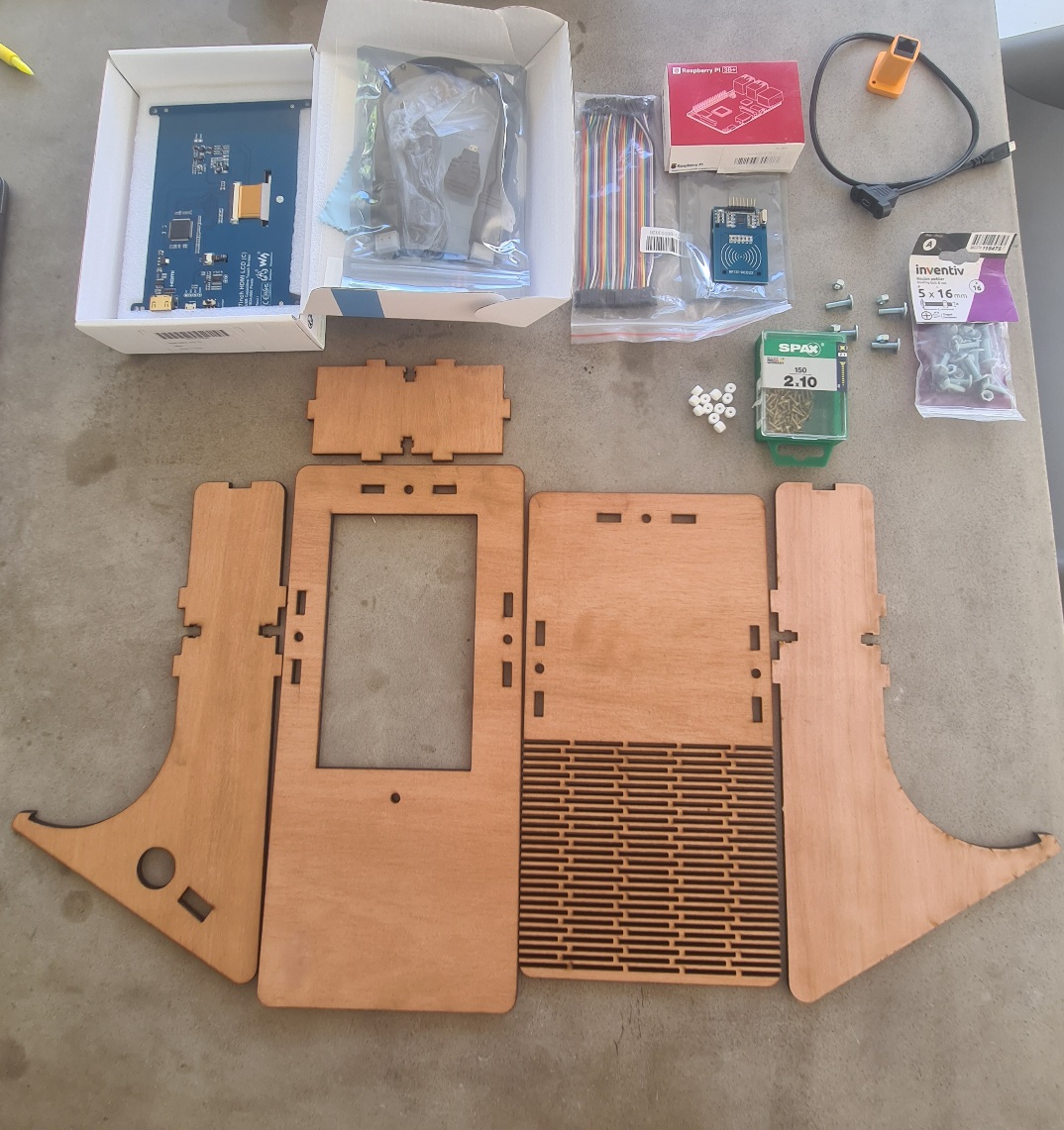
To this :
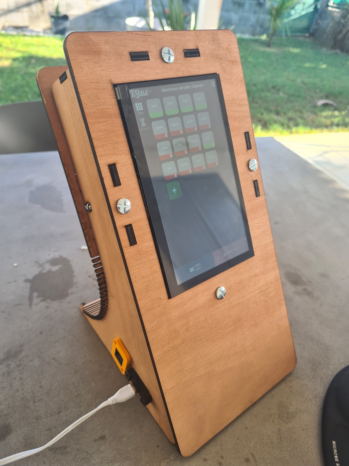
> Here it's for 7inch screen
> At the end we will see the differents step betwen 7inch screen an 10inch
To do this we need folowing thoses steps :
1 Lazer cut the body
2 3D-print accessories
3 Software install on Raspberry
- 3.1 intall Raspberry Pi OS (Legacy,32-bit) Lite
- 3.2 Download and launch the script to install: "LaBoutik"
4 body assembly 7inch
- 4.1 Cabling and test
- 4.2 finish assembling
5 body assembly 10inch
6 Troubleshooting
Here the Bill of Materials :
1 X Access to FABLAB with :
3D printer
Lazer cut able to cut 5 milimeters plywood
1 X raspeberry PI3B +
1 X Power supply for Raspberry
1 X micro SD cards (8Go mini)
7 X " Dupont " cables
1 X NFC card reader ( RC522 )
1 X USB capacitive touch screen : Waveshare 7inch HDMI LCD ( C ) (or 10.1inch HDMI LCD(G) )
1 X Plywood 5 mm ( qty depend if 7 or 10.1 inch)
1 X box of 2X10 universal screw
1 X box of Roofing bolt & nut 5X16
1 X precision screwdriver
1 X WIFI LAN (with admin acces to the BOX in place you need to use the cashless box )
1 X computer to install Raspberry on LAN
For the 10'' screen an additional USB-MicroUSB cable .
Optionnal :
1 x Adaptateur RJ45
1 X small RJ45 Cable
1 X Adaptateur Micro USB
1 X keybord(if you have problem with SSH connection to the Raspberry)
1 X soldering iron kit ( if you by NFC card kit )
Lets go :
# 1 - Lazer cut the body :
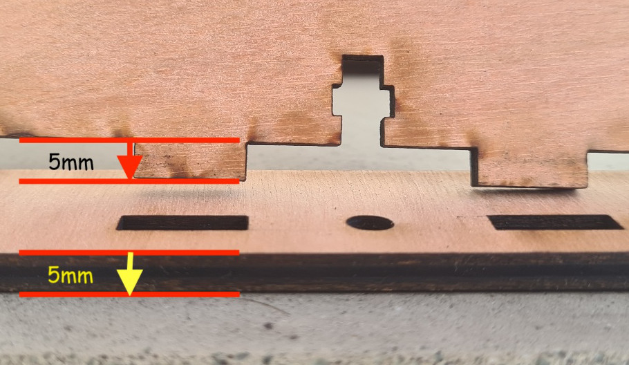
> Note : Those files are for 5mm thick plywood and for 7inch screen
> If you use 10inch screen change "7Pouces" below by "10Pouces"
> we will see differences at the end of this document .
----
> If you use different thick than 5mm you will need to modify the plans slightly to modify the length of the lugs.
----
Go to :
https://github.com/TiBillet/DIY-point-of-sale-hardware/tree/main/7Pouces/7PoucesFixationArriere
You can find :
- Plans repository to see the dimensions used and reproduce if necessary in your CAD software .
- Freecad repository to modify then with [Freecad](https://www.freecad.org) files to modify if you need .
- dxf_files repository to modify then with another CAD software if you need .
- lightburn repository to send then directly to your lazer cutting machine with [lightburn](https://lightburnsoftware.com/).
> NOTE : you need to cut 2X "Cote7Pouces.lbrn2" , if you are using connectors for the network and power supply, make holes to the size of your connectors on one side.
If you don't need to modify ( you have exactly this screen) , you can download the [lightburn repository](https://github.com/TiBillet/DIY-point-of-sale-hardware/tree/main/7Pouces/7PoucesFixationArriere/lightburn),
then send the files for laser cutting .
TODO :
- add 2 sides: 1 with a simple hole for the passage of cables .1 with holes for connectors
- quick explain export to lightburn from freecad, fusion and lightburn parameters
# 2 - 3D-print accessories :
This step is optional, but strongly recommended.
It will allow you to have a support for the Raspberry. This can be fixed to the wood directly inside the case, but this does not facilitate maintenance or cooling, and there is a risk of scratching the soldering.
In addition, you can use the smallest screws, which are fairly easy to find in the main DIY shops (the minimum size is usually 10mm).
you will have spacers to prevent the screws from passing through the plywood .
Download the STL files from [3D-print-accessories](https://github.com/TiBillet/DIY-point-of-sale-hardware/tree/main/3D-print-accessories) repository .
Open the files in cura (or another slicer) and send them to your 3D printer.
TODO : CURA parameters
# 3 - Software install on Raspberry :
Prerequisite:
- If you don't have an ssh key on your computer, create one: open a command prompt and type :
``` ssh-keygen ```
- Download raspberry imager : https://www.raspberrypi.com/software/
- Make sure you can connect a micro SD card to your computer .
## 3.1 - intall Raspberry Pi OS (Legacy,32-bit) Lite :
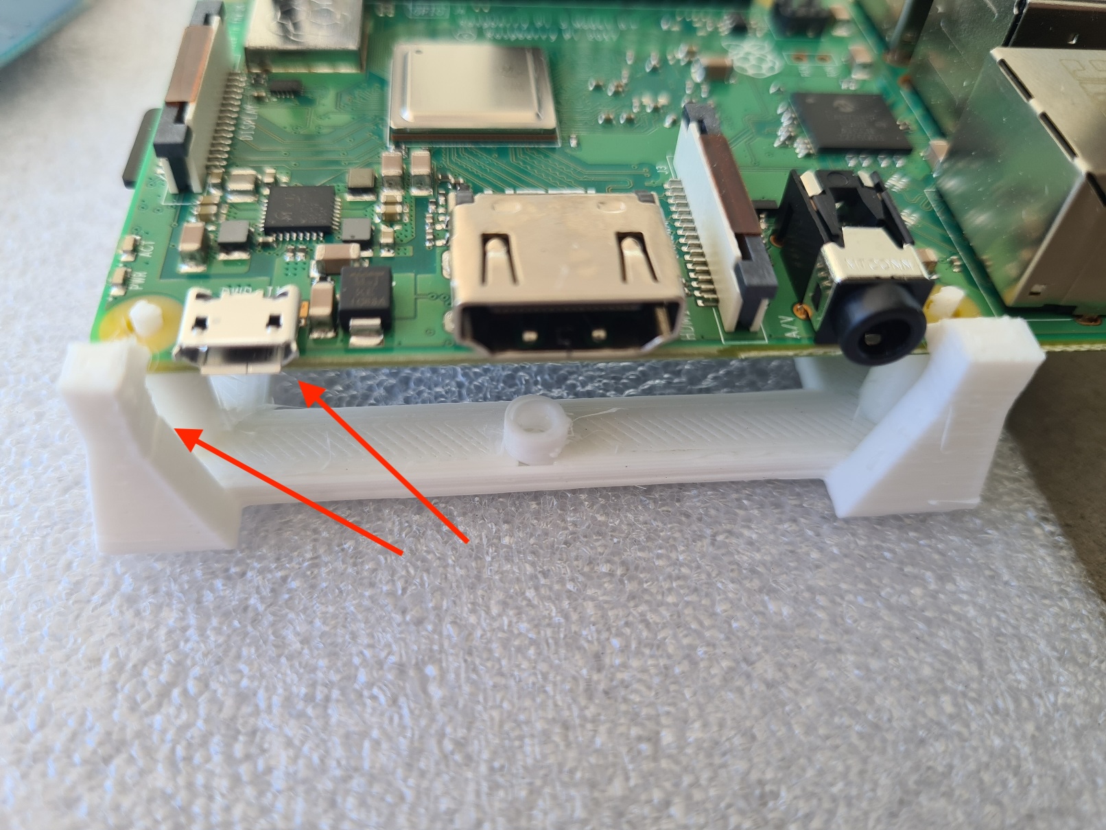
Before doing so, I advise you to place the Pi on the simply support that has been 3D printed previously, to avoid contact with the table and any screws or other objects that might be on it.
> Note : place the power connector on the narrowest corner.
Open raspberry imager and chose model "Raspberry Pi 3" :
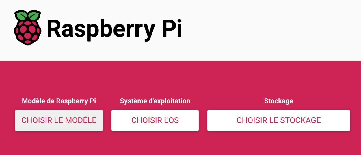

Choose Raspberry Pi OS(Other) :

And choose Raspberry Pi OS (Legacy,32-bit) Lite :

Then choose your SD card inserted in your computer :

Click Next , and the following screen appears:

Click on "MODIFIER LES REGLAGES".
In the "GENERAL" tab:
Enter :
- The host name (of your choice but not already present on your LAN)
- WARNING The user name must be "sysop" and nothing else
- The password of your choice
- Your wifi settings
- Your local settings .
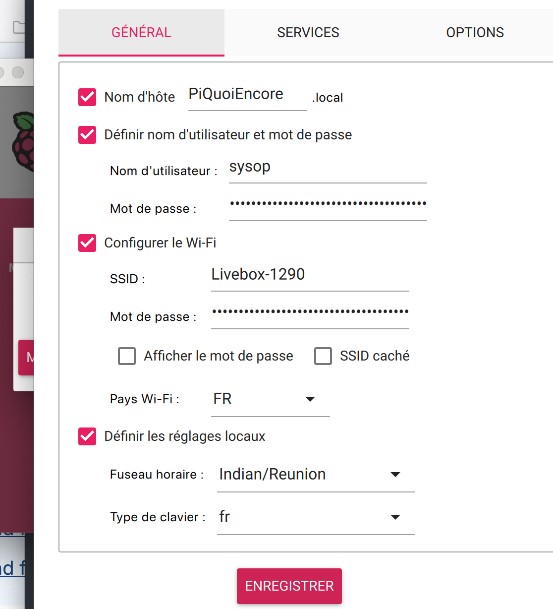
In the "SERVICES" tab:
Click on "Authentification via clef publique"
and paste your public key (not your private key!!) which is usually found in :
/Users/YourNameUser/.ssh/id_rsa.pub
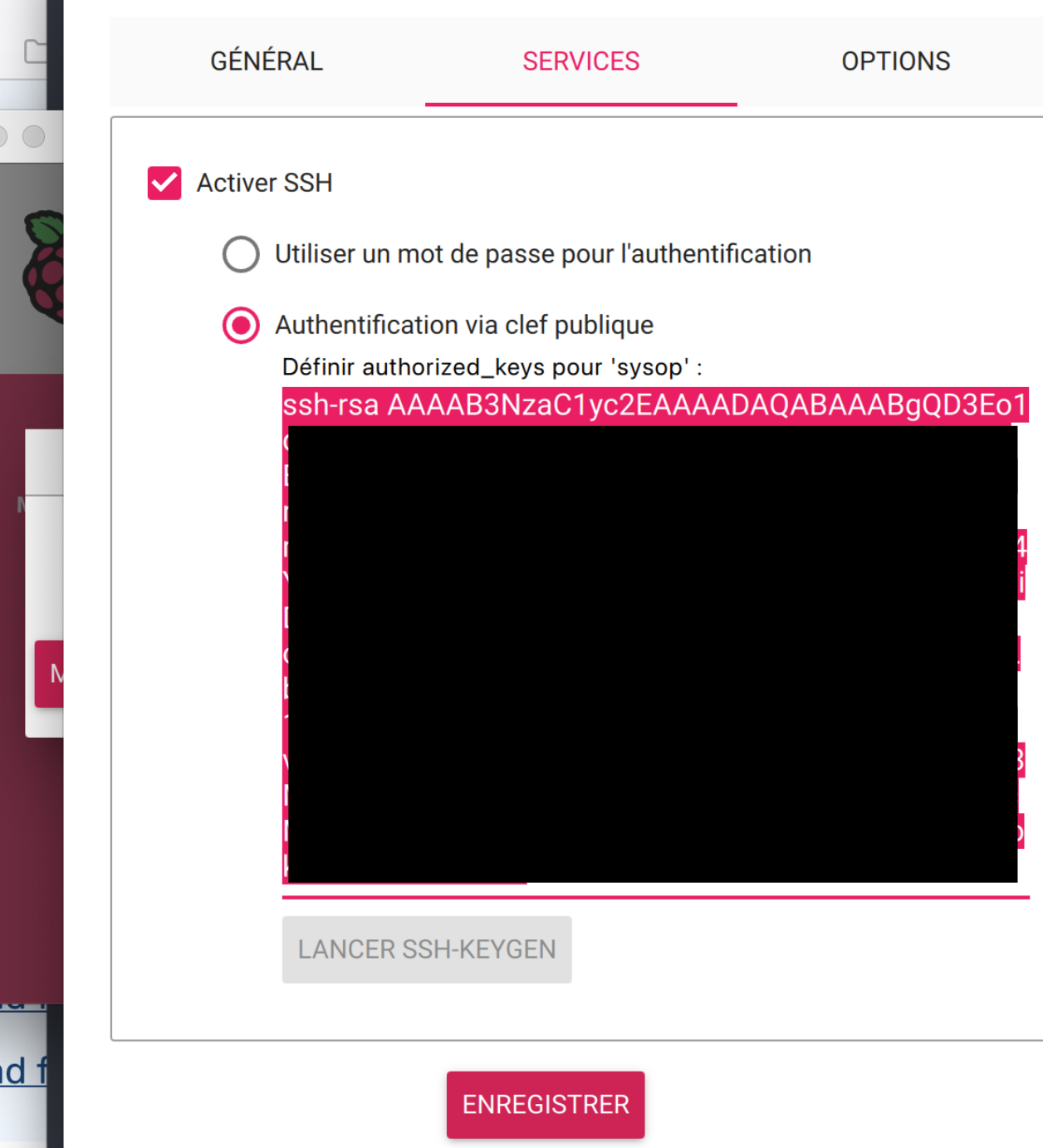
Click on "Save".
The message reappears:

Click on "OUI"

Click on "OUI"
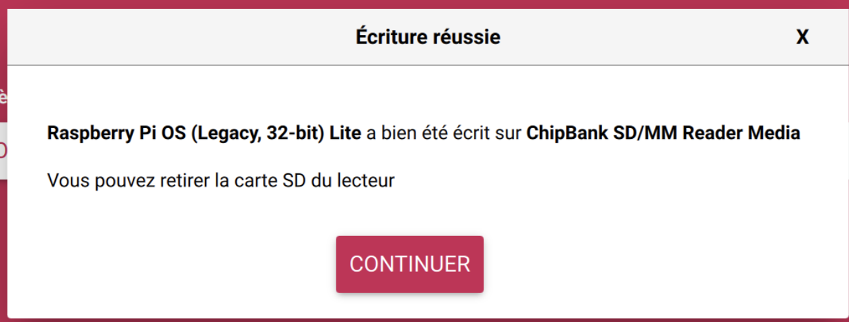
Please allow 10 to 20 minutes for your SD card to be created, depending on your bit rate and whether the image has already been downloaded to your PC.
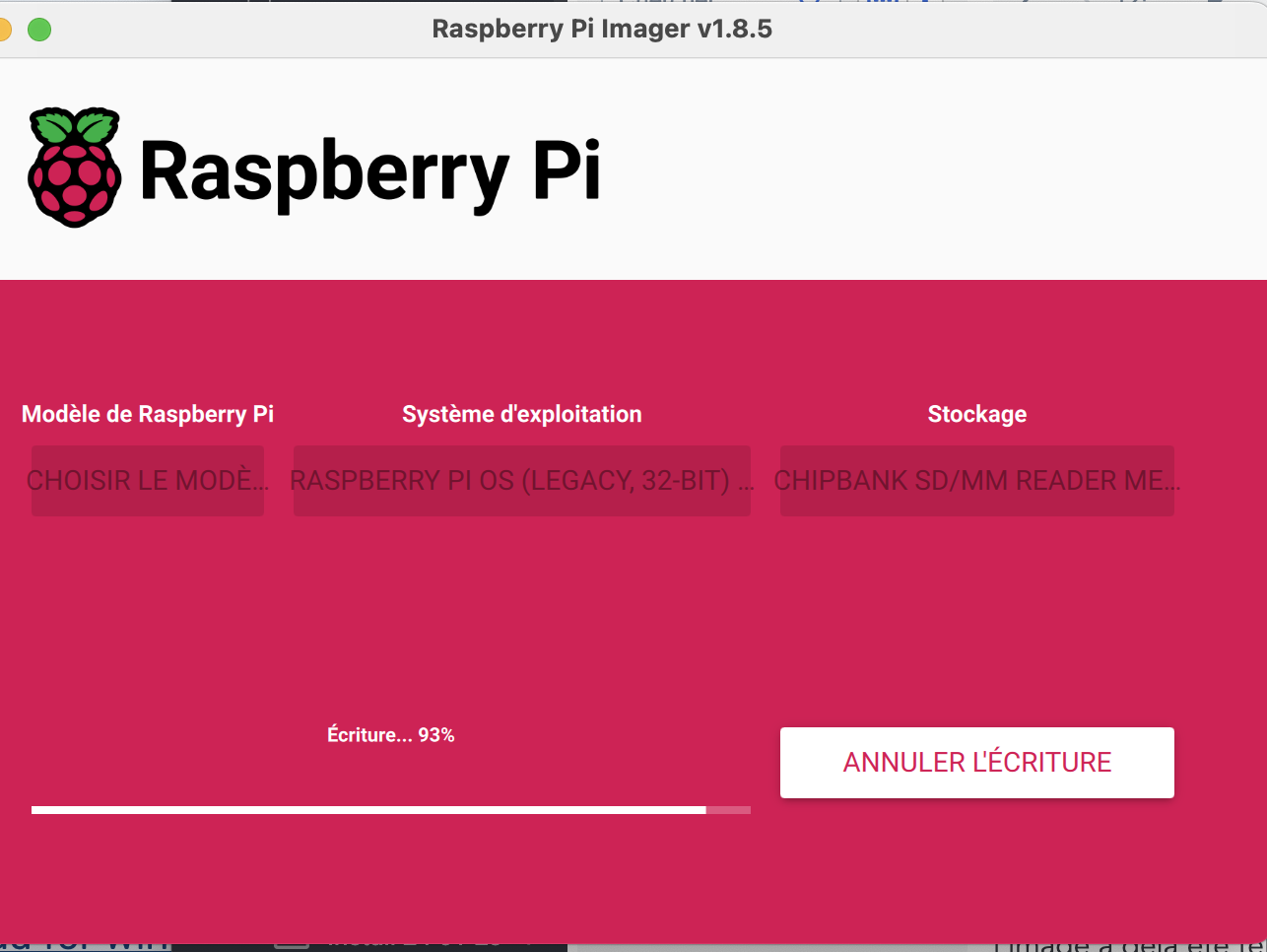
Once finished, click on "CONTINUER".
- Remove your SD card and insert it into the Pi (the Pi must not be powered, of course :) )
- Now power your Pi , wait , the green LED is blinking , it will start , then reboot .
- Go to your BOX, in the amin interface to look for its IP address . As long as you are in the admin interface of your Box, you can assign it a fixed IP, this is done in DHCP by fixing the IP address to the MAC address of your Pi. This way it will always keep the same IP address.(No screenshots here, as this depends on your router).
- On your PC, open a terminal , and type:
```ssh sysop@IPofYourPi```
the message appear :

type : "yes" .
You are now connected to your Pi :+1:
## 3.2 - Download and launch the script to install: "LaBoutik" :
- Always connected via SSH on the Pi, type :
```
curl -O https://raw.githubusercontent.com/TiBillet/client-raspberry-cashless-LaBoutik/main/LaBoutik.sh
chmod +x LaBoutik.sh
```
TODO : the following will change ASAP
```
sudo ./LaBoutik.sh pasword token https VotreDomaine.cashless.tibillet.re 3 gpio
```
Take a coffe , or start building the body for the next stage .
# 4 -body assembly
Your plywood body should now be ready.
> To avoid getting your hands and plywood dirty. Clean the laser-cut edges. Laser cutting burns the plywood and forms a layer of carbon.
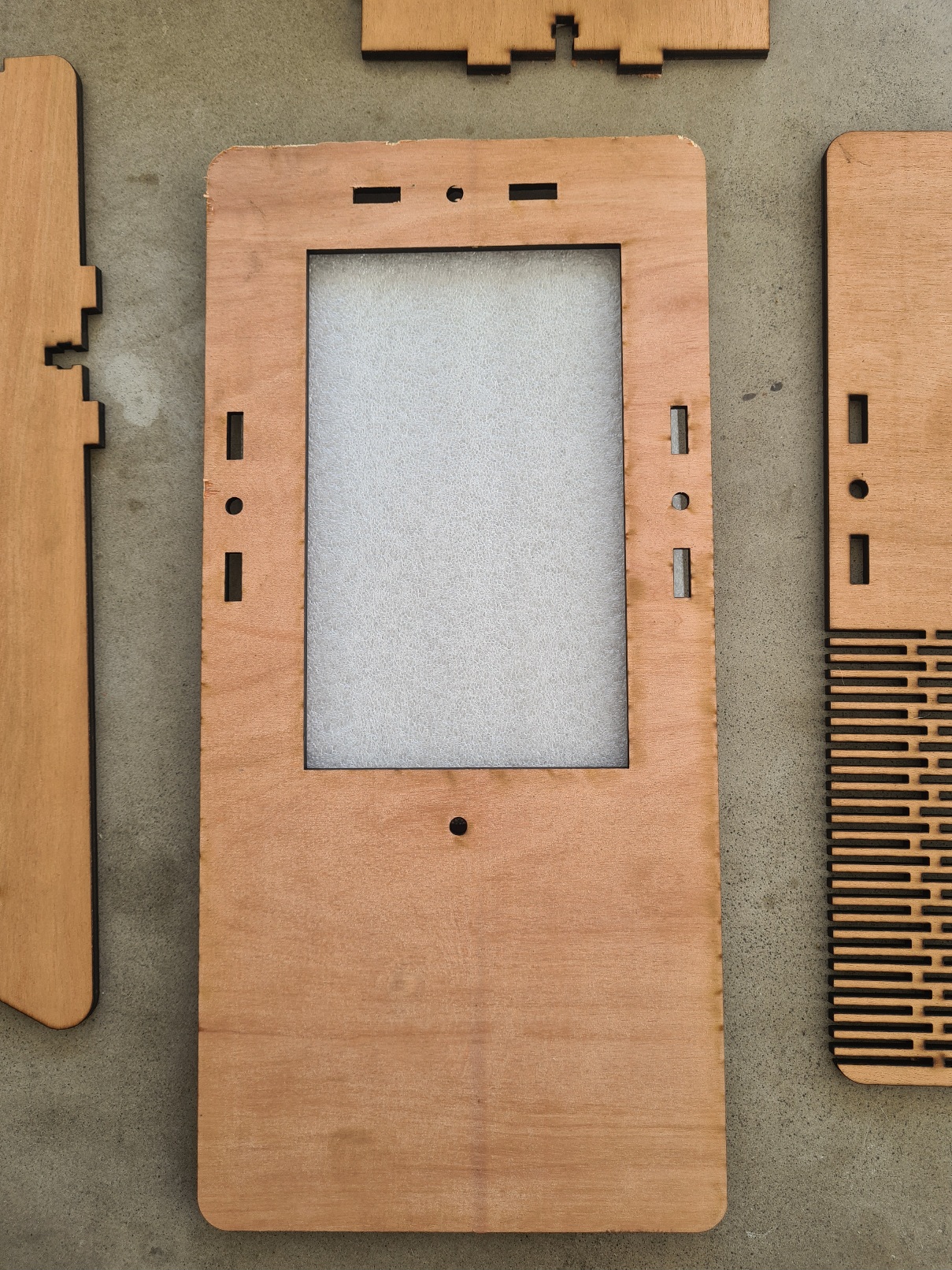
- Place the foam protection supplied with the screen on the underside of the front panel :
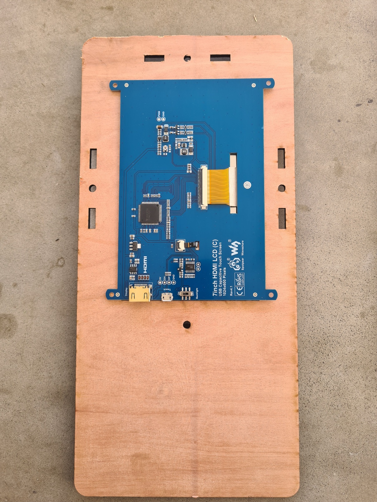
- put the screen like this :
- Check the length of your screws :
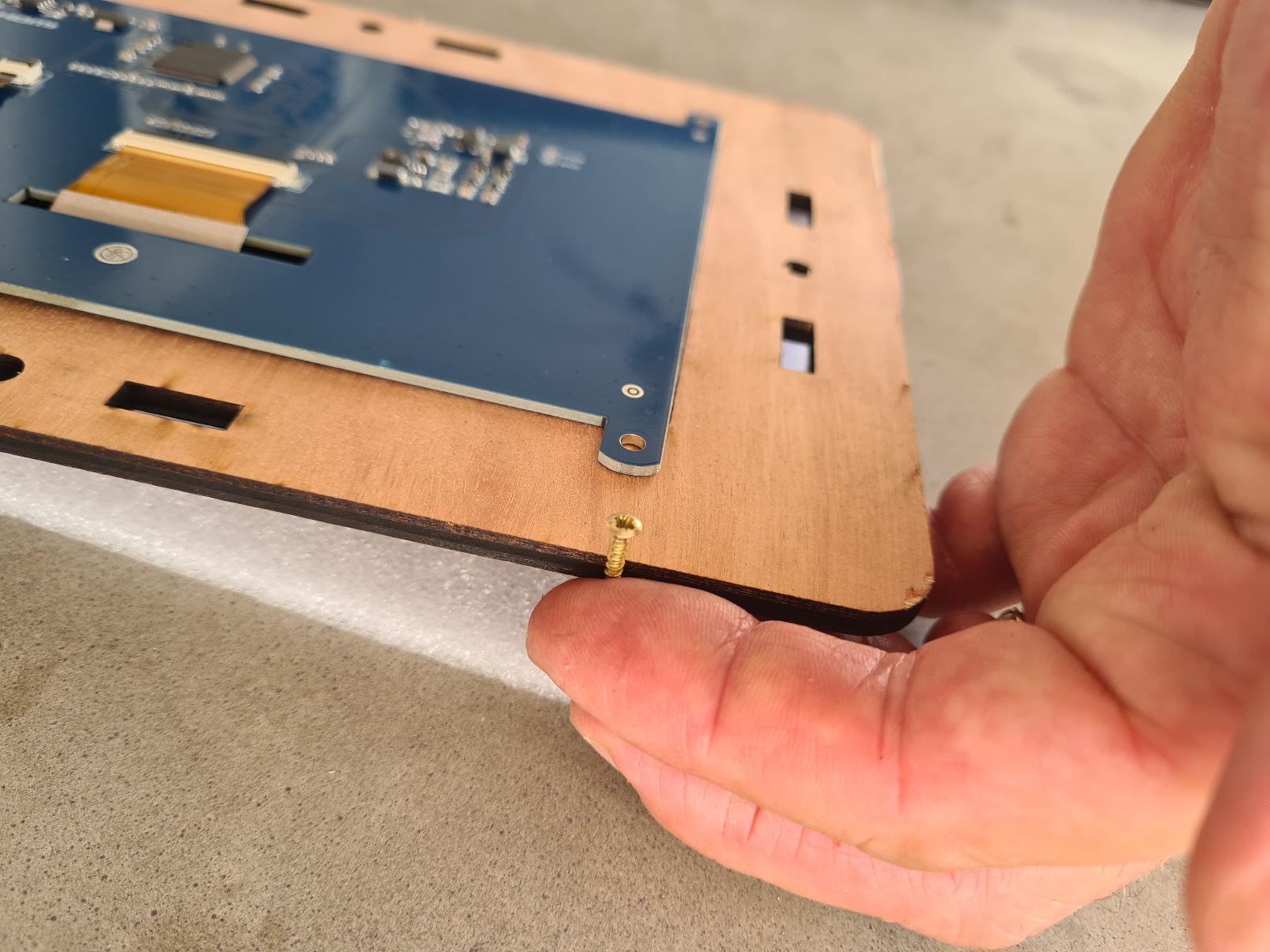
- Choose the appropriate spacer, 3D printed beforehand, so that the screw does not protrude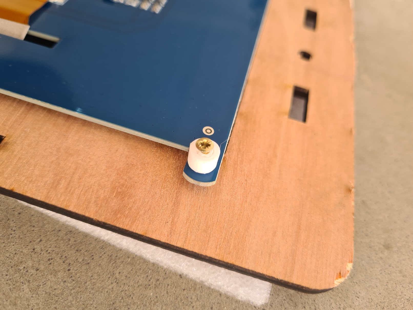
:
- Screw in the 4 screws using a suitable screwdriver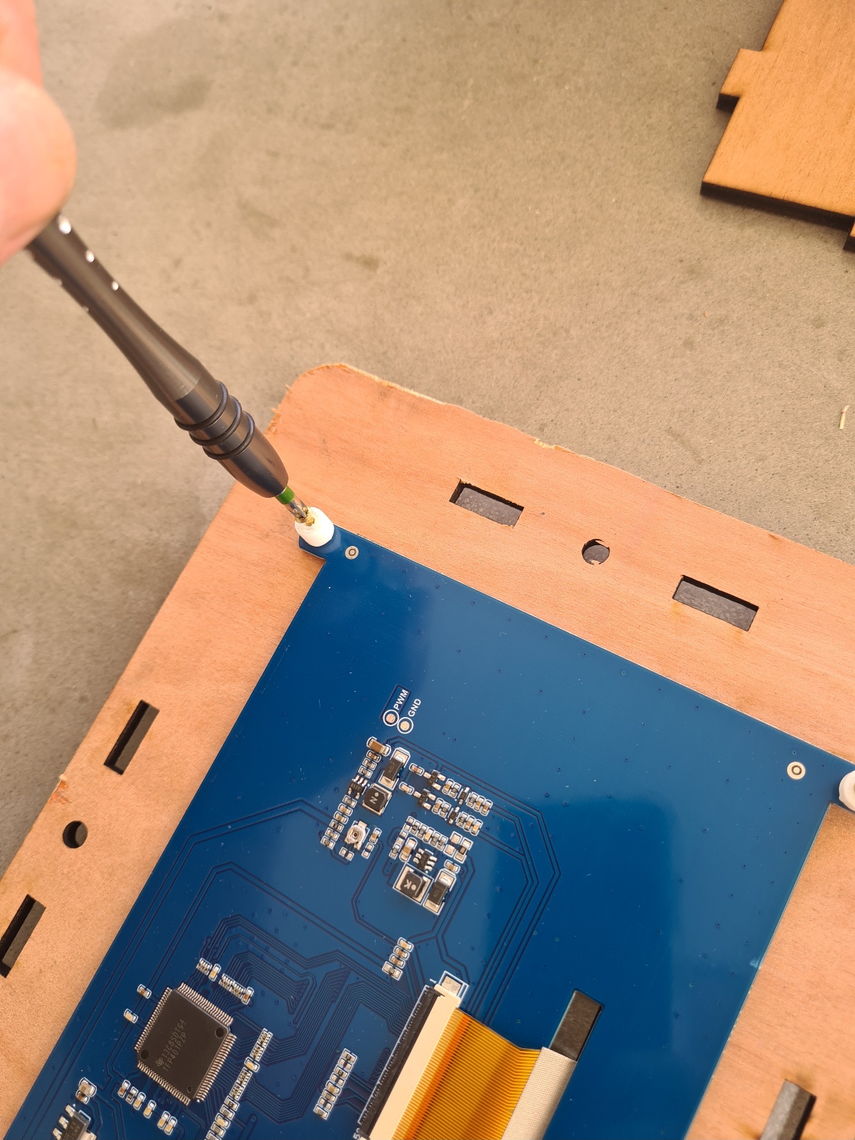
TODO : monter les 3 options : sans passage de cale ( passage par l'arriere ), avec juste un trou pour le passage ( faire un adaptateur en 3D),Passage de cable avec connecteurs .
- Place one of the 2 sides in the notches as shown below :
If you have opted for a side cable entry, choose the side that suits you best.
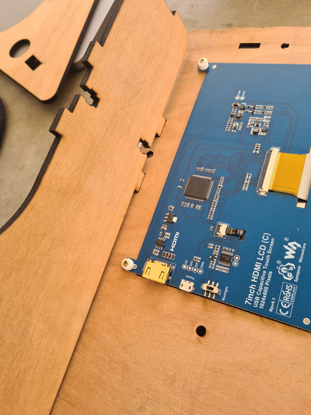
-Use a Roofing bolt & nut 5X16 to secure the side to the front panel, but do not overtighten. The side must be able to move slightly: 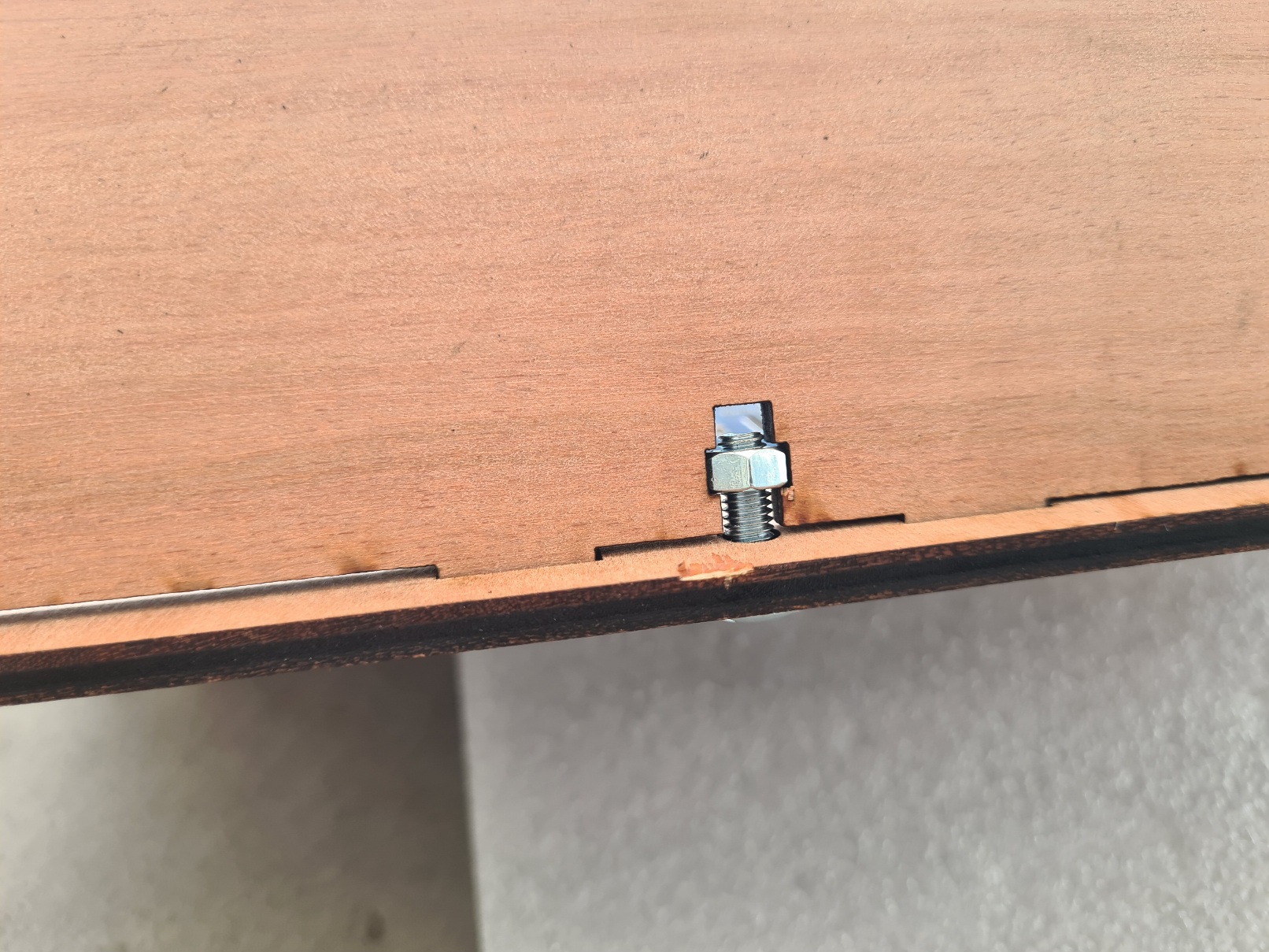
- Place the top in the notches:
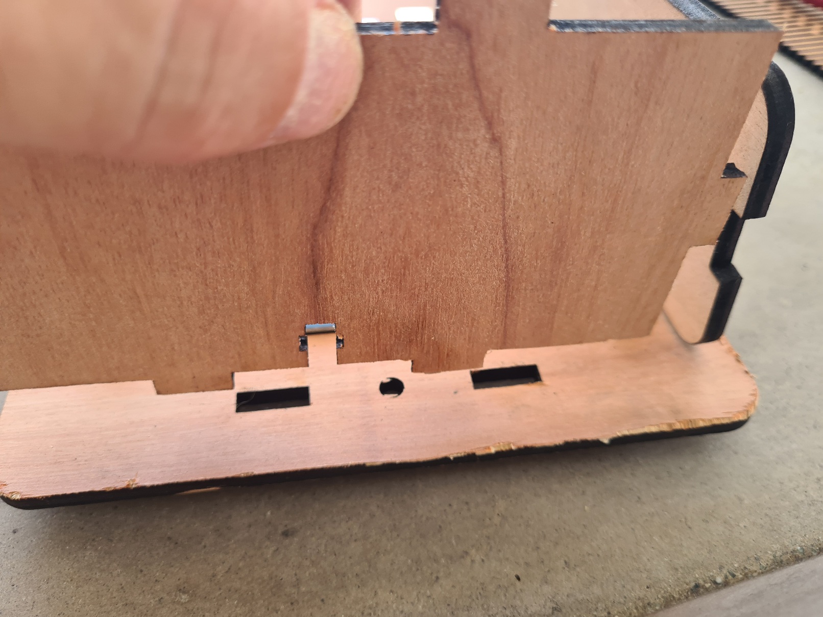
-Use a Roofing bolt & nut 5X16 to secure the top to the front panel, but do not overtighten. The top must be able to move slightly:
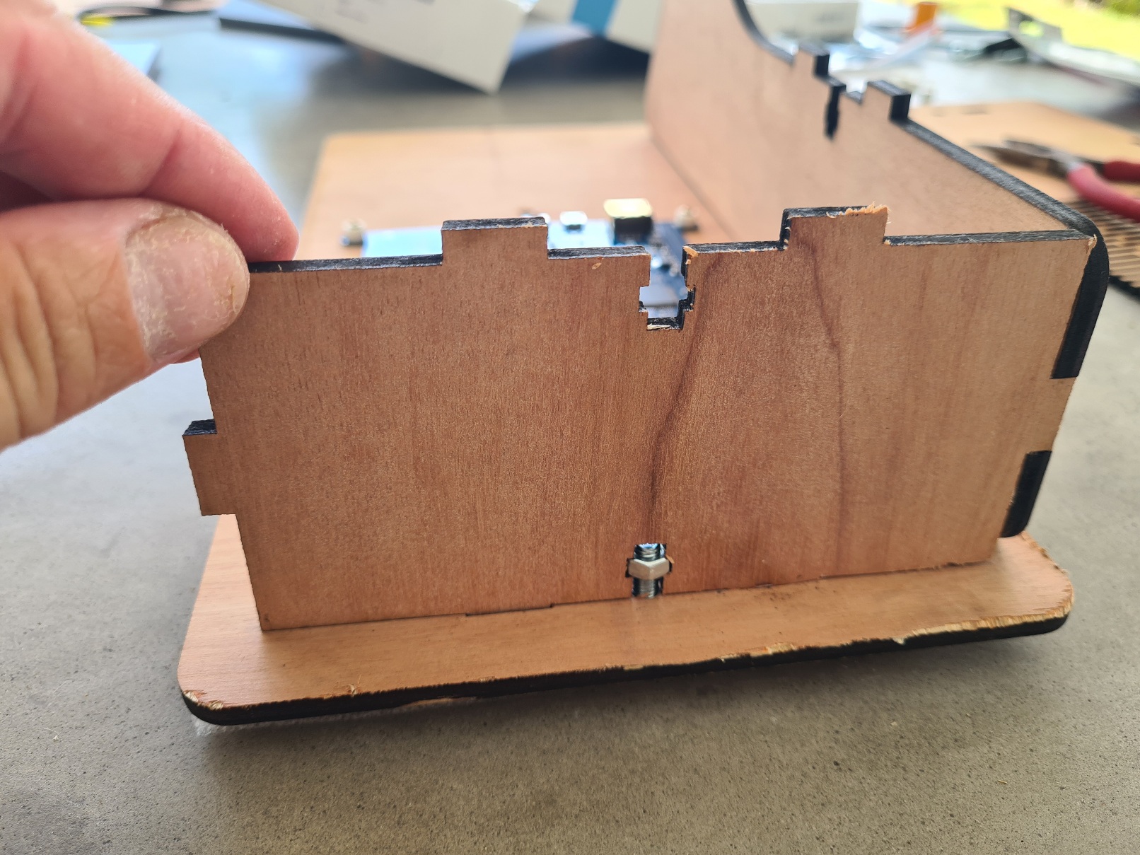
- place the second side in the notches and use a Roofing bolt & nut 5X16 to secure the side to the front panel, but do not overtighten. The side must be able to move slightly : 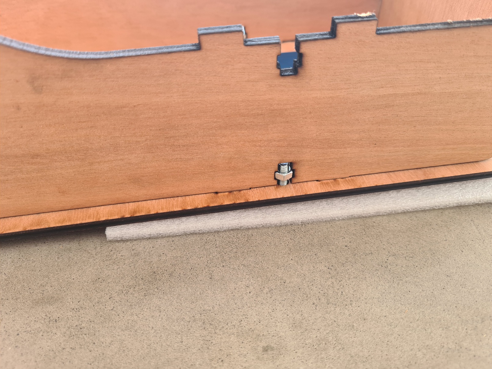
Now the body is almost finished :
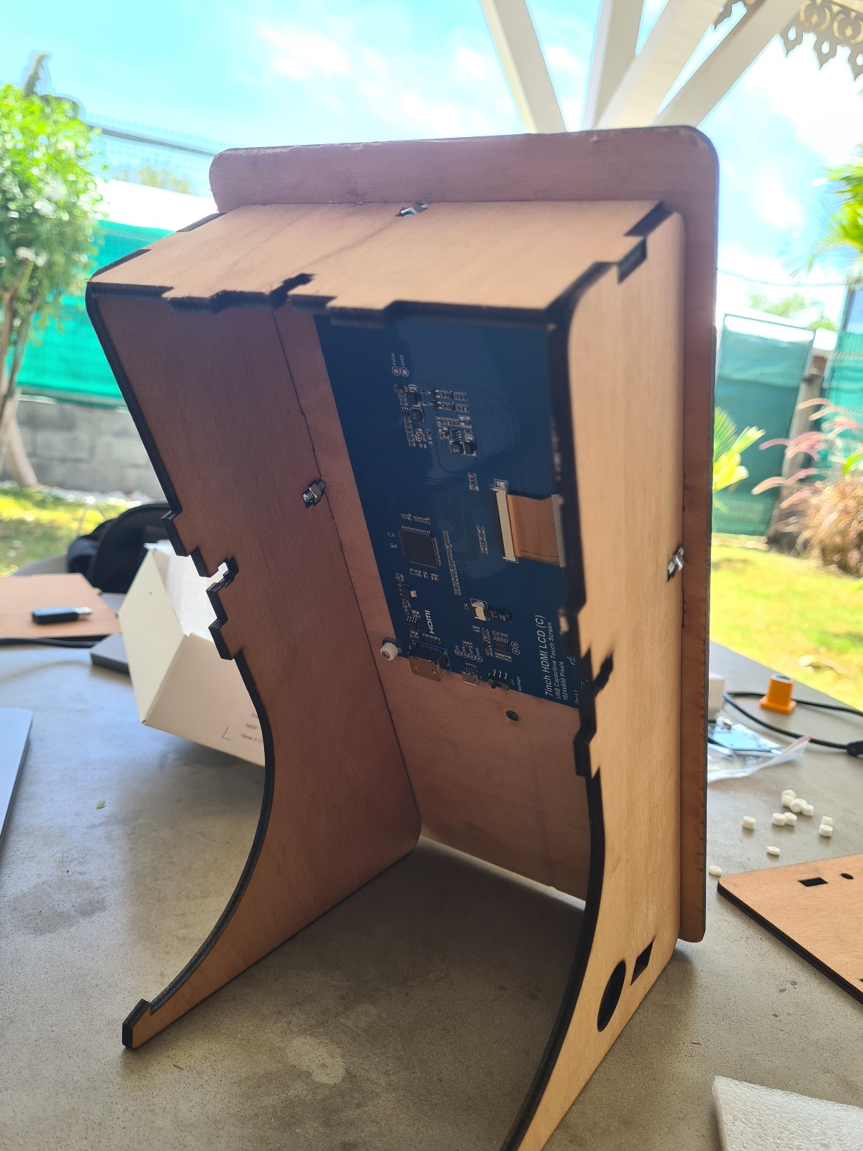
## 4 body assembly
## 4.1 Cabling and test
----
> Warining : For these steps the Raspberry must not be powered if I'm not telling you.
----
We're now going to wire up the NFC reader, the Pi and the screen.
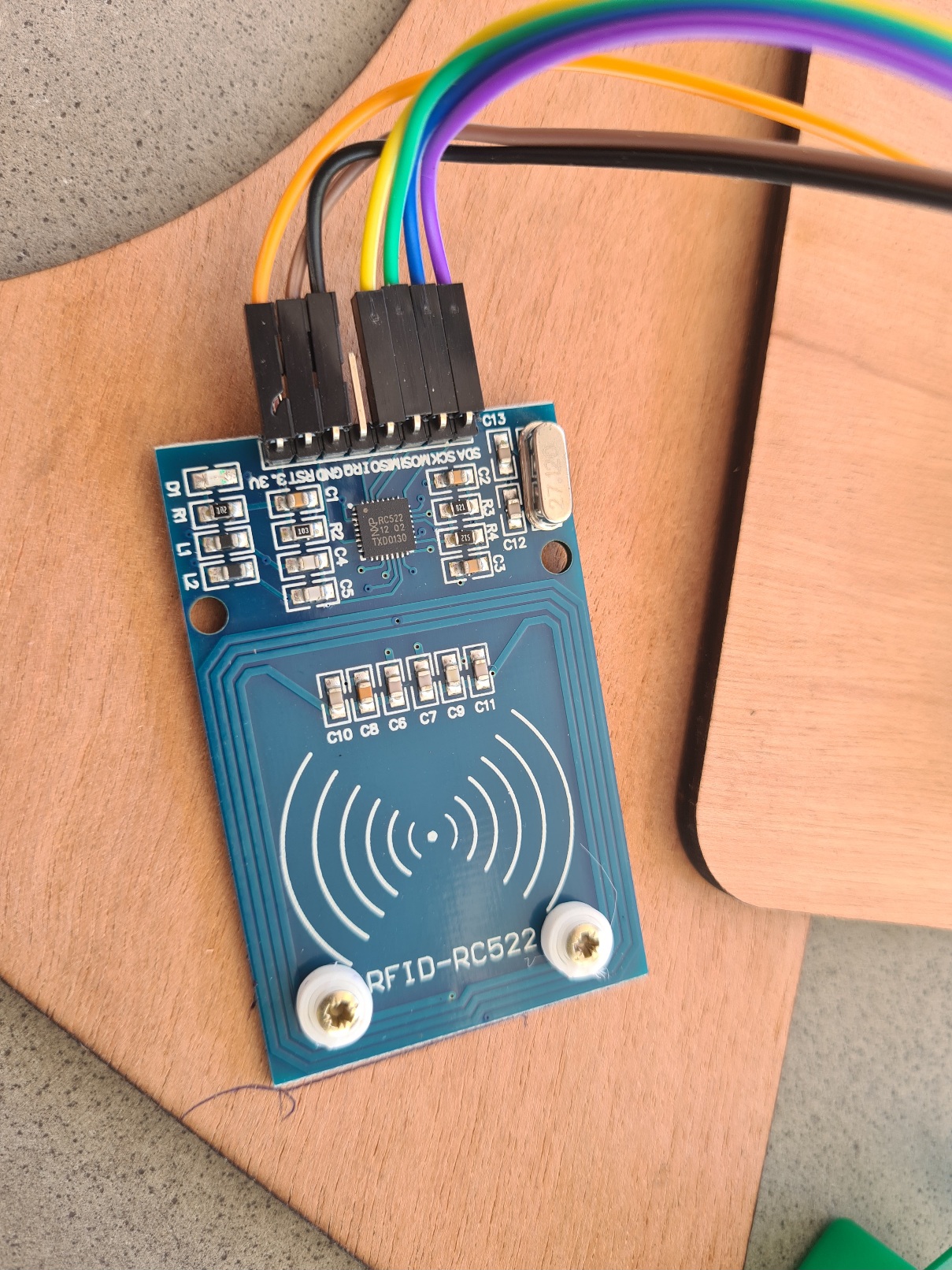
On the NFC reader, connect the cables as shown below:
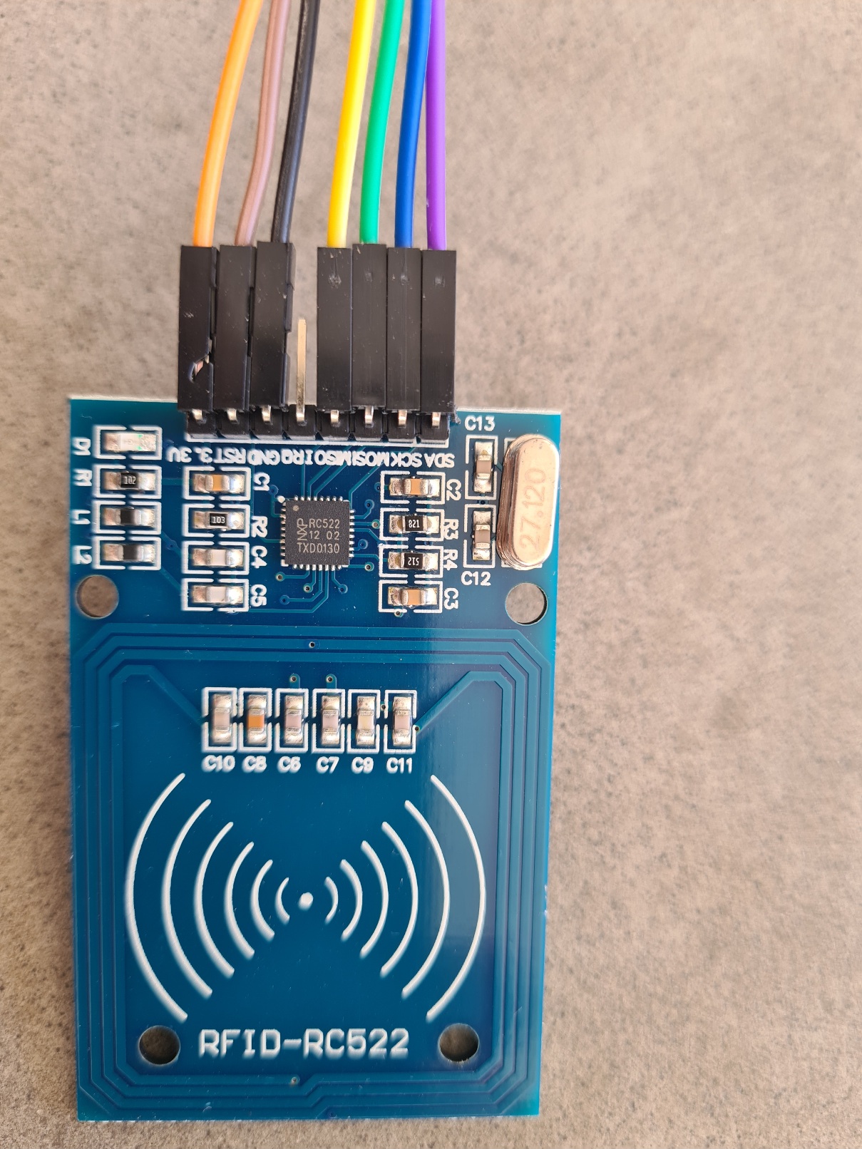
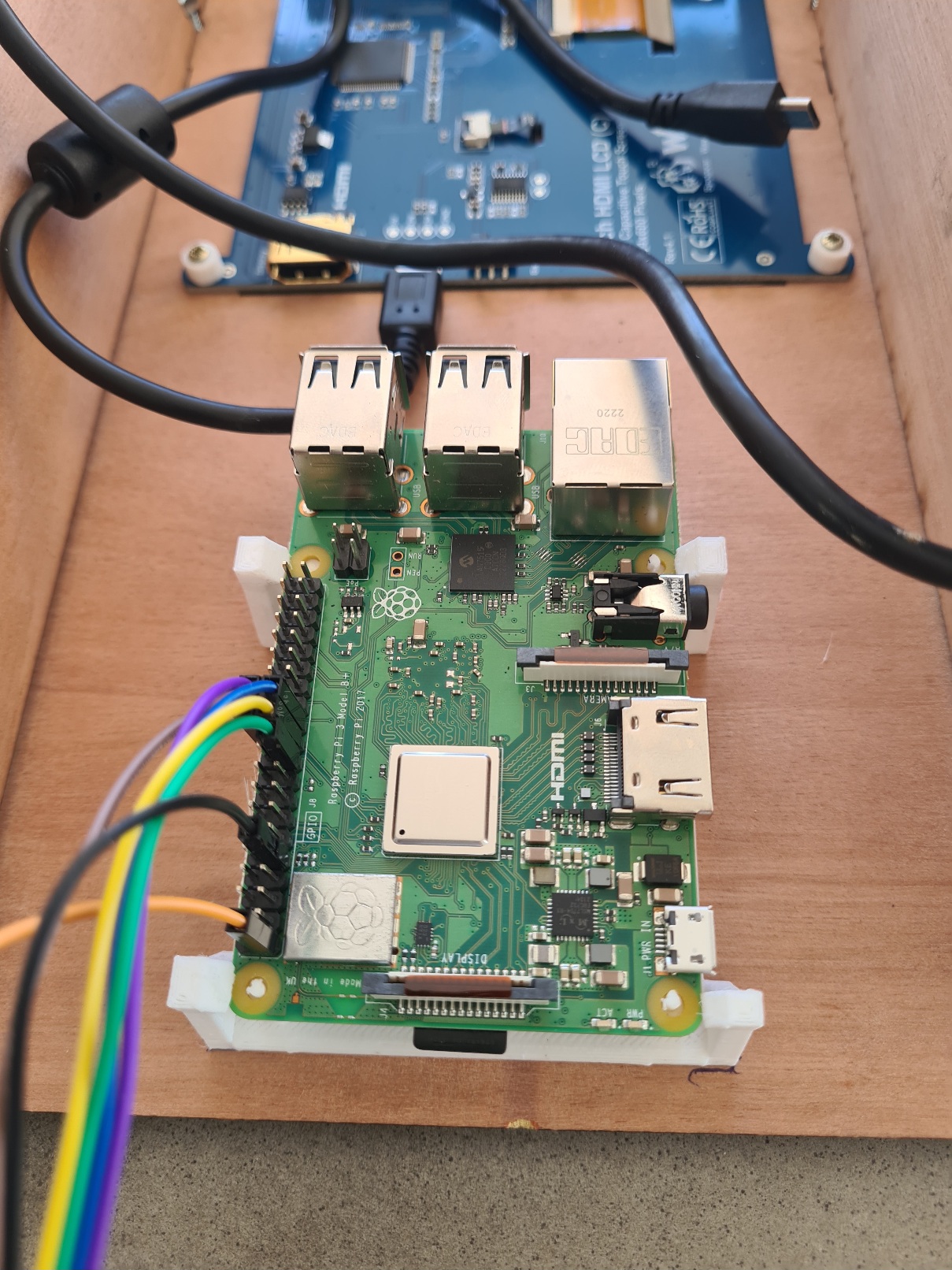
On the Pi, connect the cables as shown below:
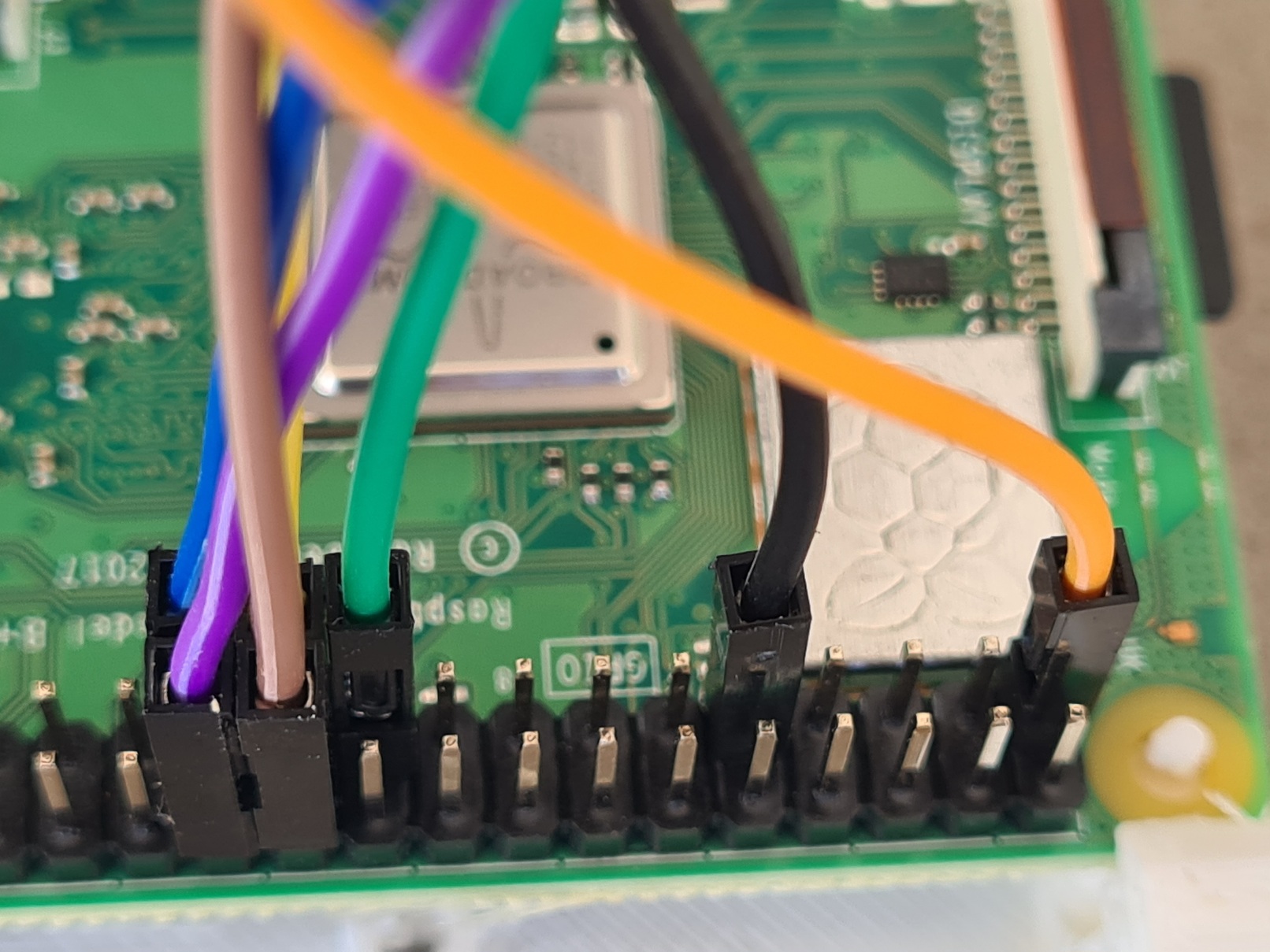
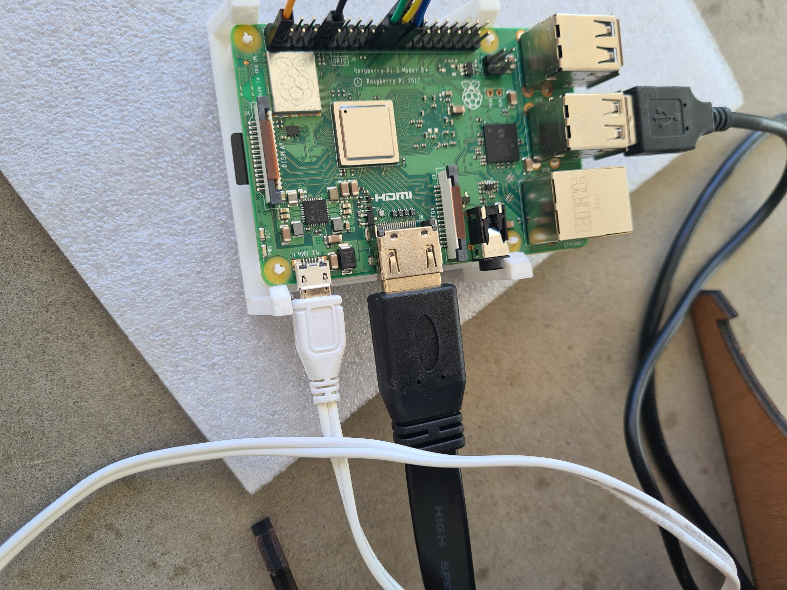
On the screen, connect the HDMI cable and the microUSB-USB cable supplied.
On the Pi , connect the HDMI cable and the microUSB-USB cable to one of the USB ports and the power cable .
You can now connect the Pi's power supply .
After a few seconds, the following screen appears:
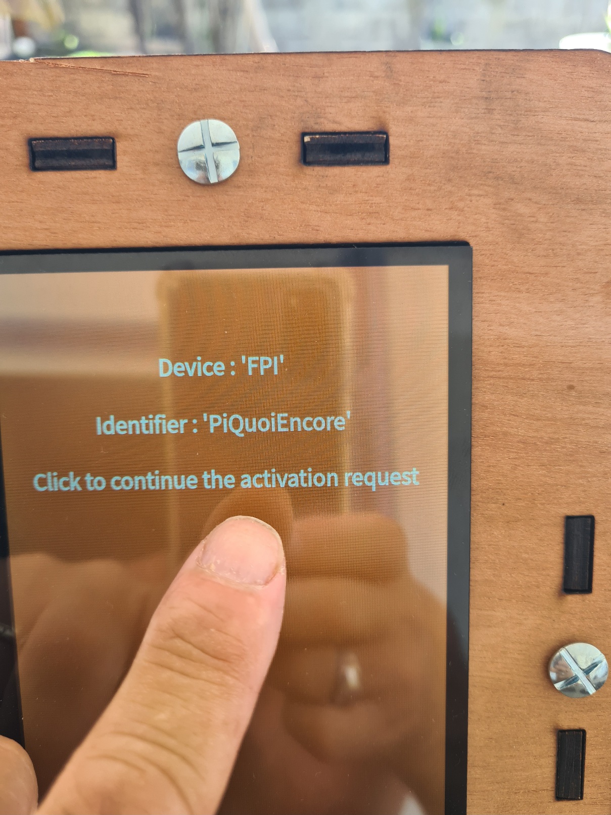
Click on the screen and follow this step :
TODO : Under modification
On the Admin interface :
Click on "Devices" on the left
Search your device , and Click

Click on save .
Now you have this screen :
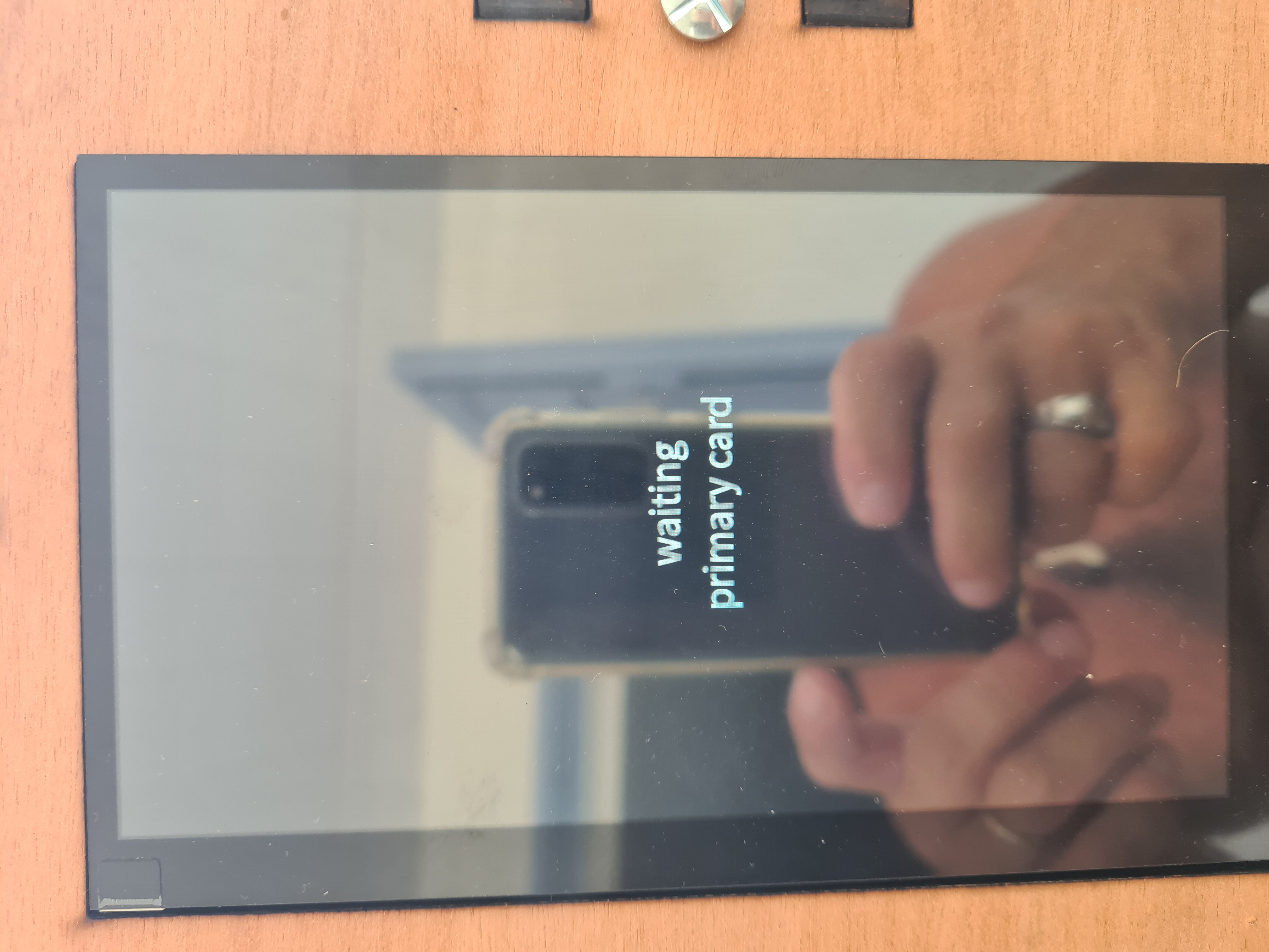
Follow this link to create a primary card :
https://tibillet.org/fr/docs/Utilisateur/Cashless/admin_add_primary
Place your NFC card near the reader :
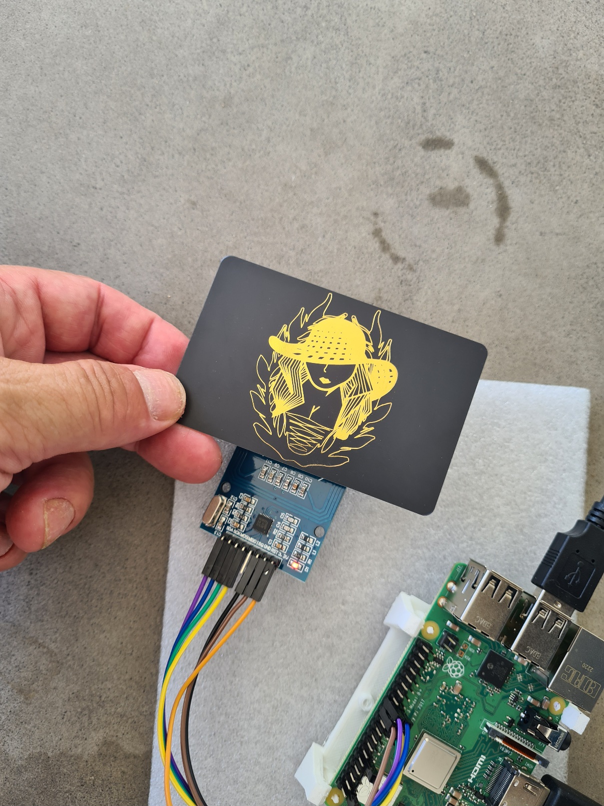
And ... TADAM :
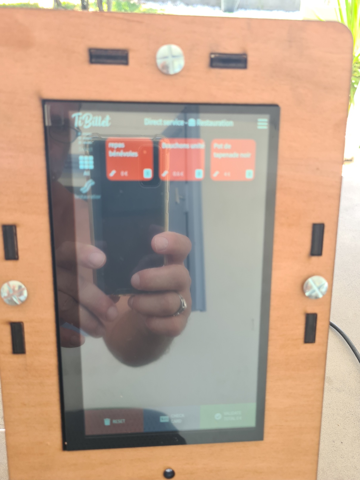
Now always in ssh on the Pi type :
```sudo schutdown now ```
Or the babarian solution disconnect the power .
## 4.2 finish assembling
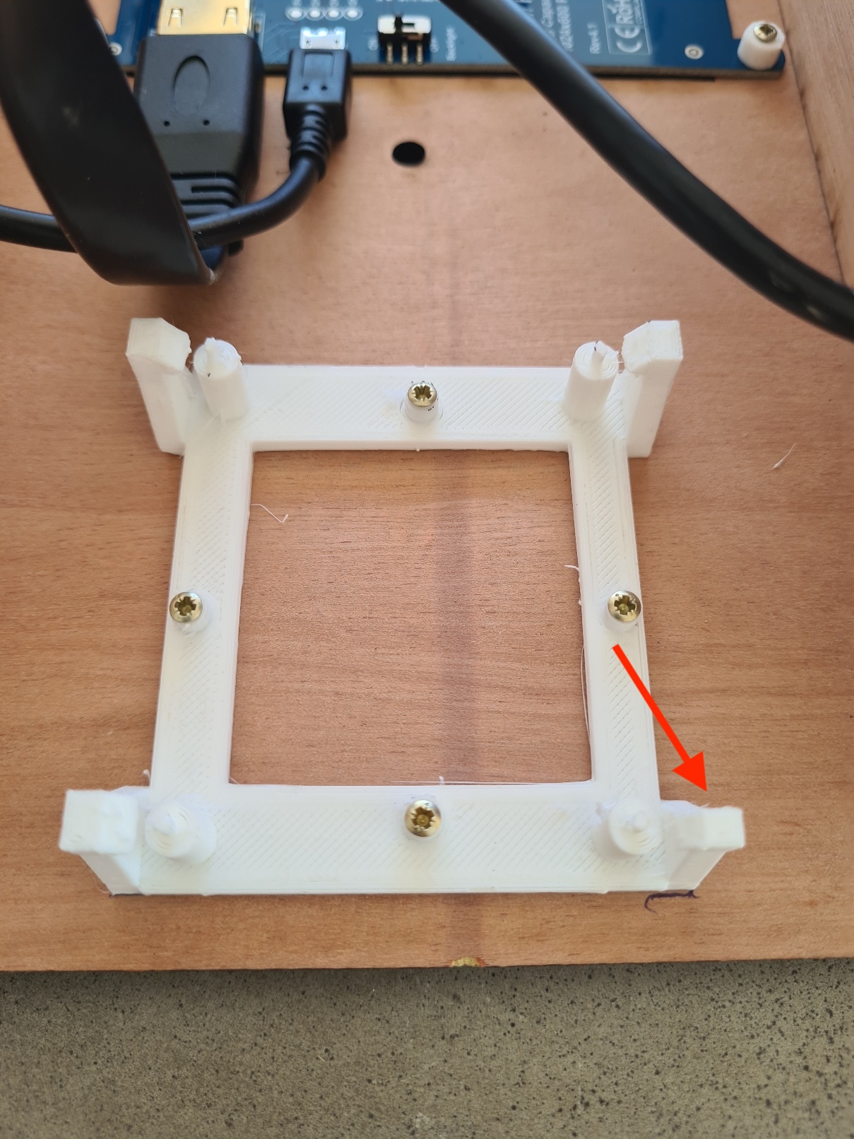
position the Pi so that the cables do not protrude, and mark 2 corners of the support with a pencil
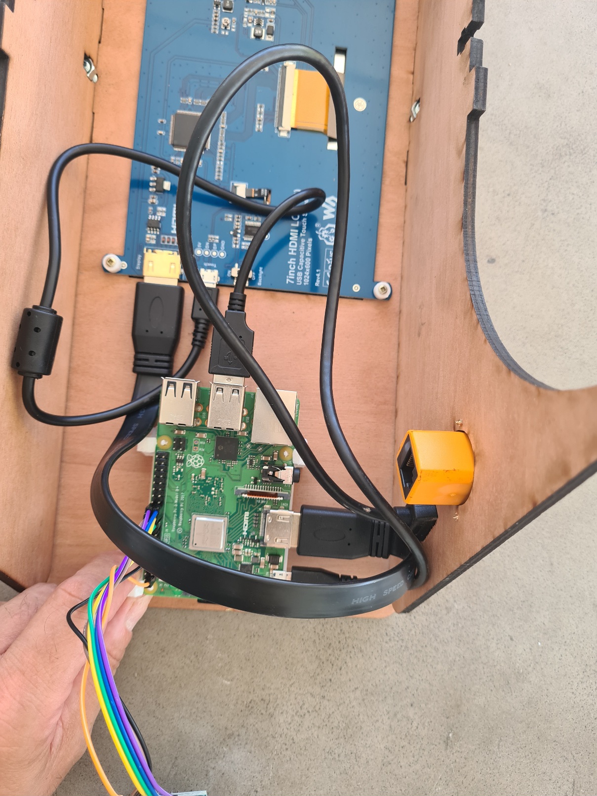
Disconnect the cables from the Rapsberry (but not the GPIOs), then fix the bracket using the 2X10 screws. No need for a spacer, the support comes with one.
> Note: Locate the corner next to the power connector on the Pi
>
place again the pi on the support :
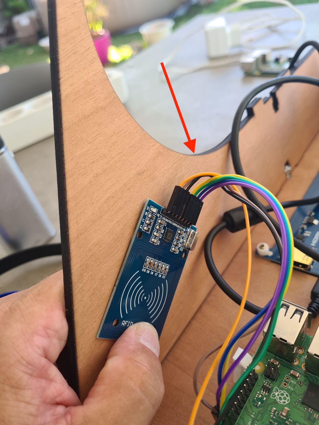
position the NFC card so that the cables do not protrude, and mark 2 corners of the support with a pencil .
> Make sure that the cables do not interfere with the rear panel assembly.
Unscrew the side to secure the NFC card. Then fix the card using the 2X10 screws and the spacers :
Replace the side ,but do not overtighten the Roofing bolt & nut 5X16 .
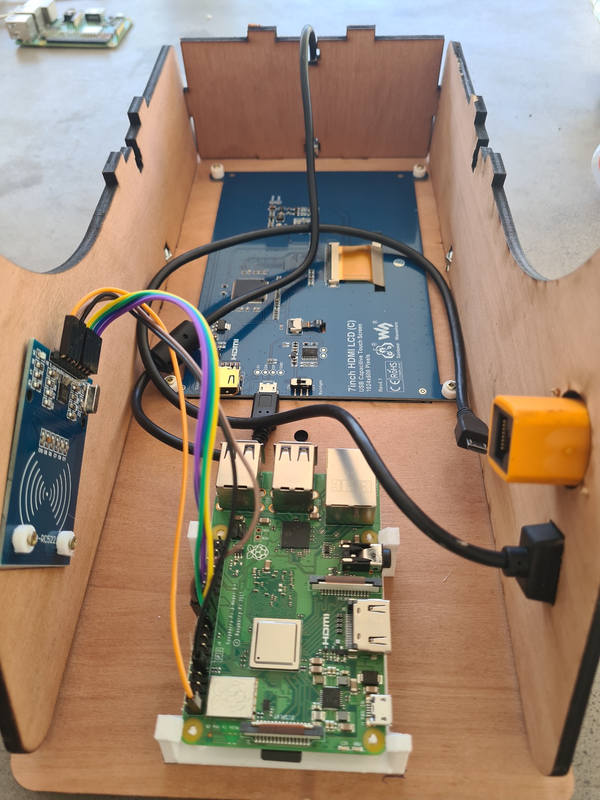
To connect the power and HDMI cable to the Pi, first dismantle the side to avoid forcing it and risking breaking the plywood.
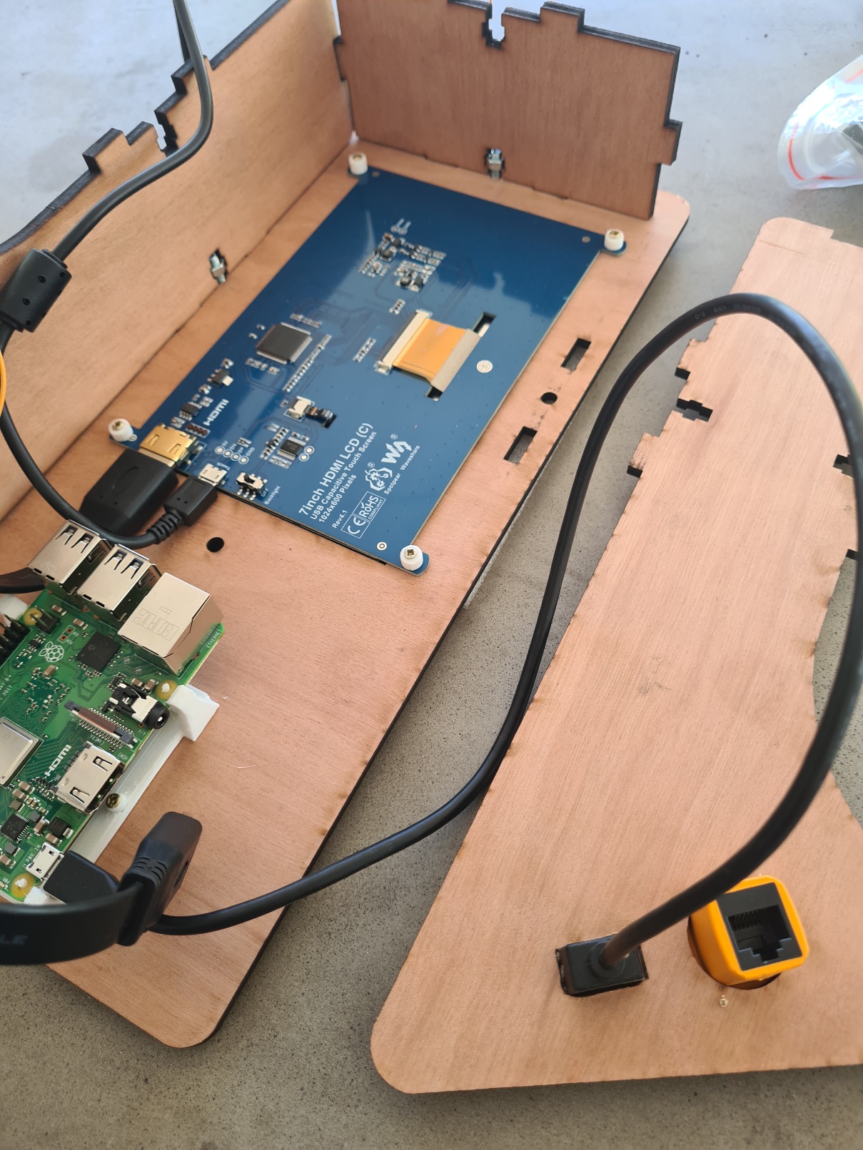
Replace the side ,but do not overtighten the Roofing bolt & nut 5X16 .
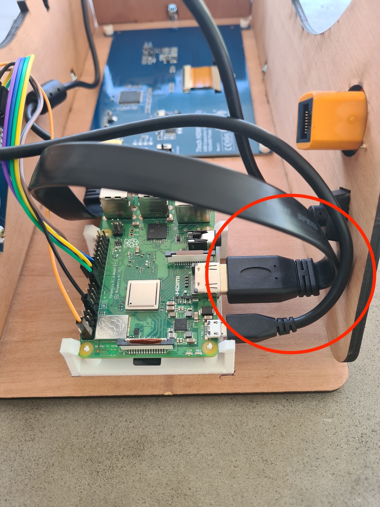
Finish cabling :
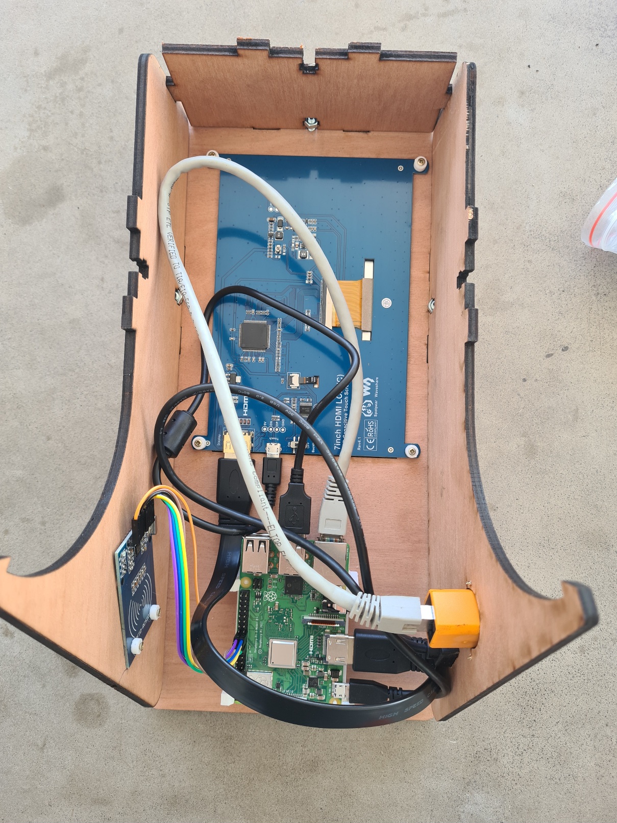
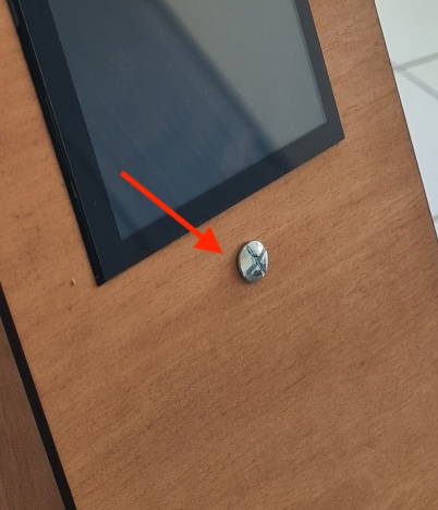
Place the last Roofing bolt & nut 5X16 on the front panel . It's just for visual symmetry.
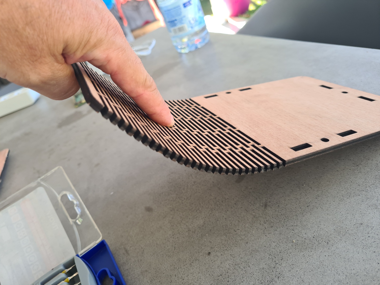
Slightly bend the part of the back face to relax the part that will be curved.
Note:
> - Don't force it, it's wood, not reed. It may break.
> - Wash your hands after this step (there will probably be some carbon released from the small cuts).
Place the rear panel in the notches (the sides must be able to move slightly, if you have tightened the Roofing bolt & nut 5X16 too much, loosen them slightly).
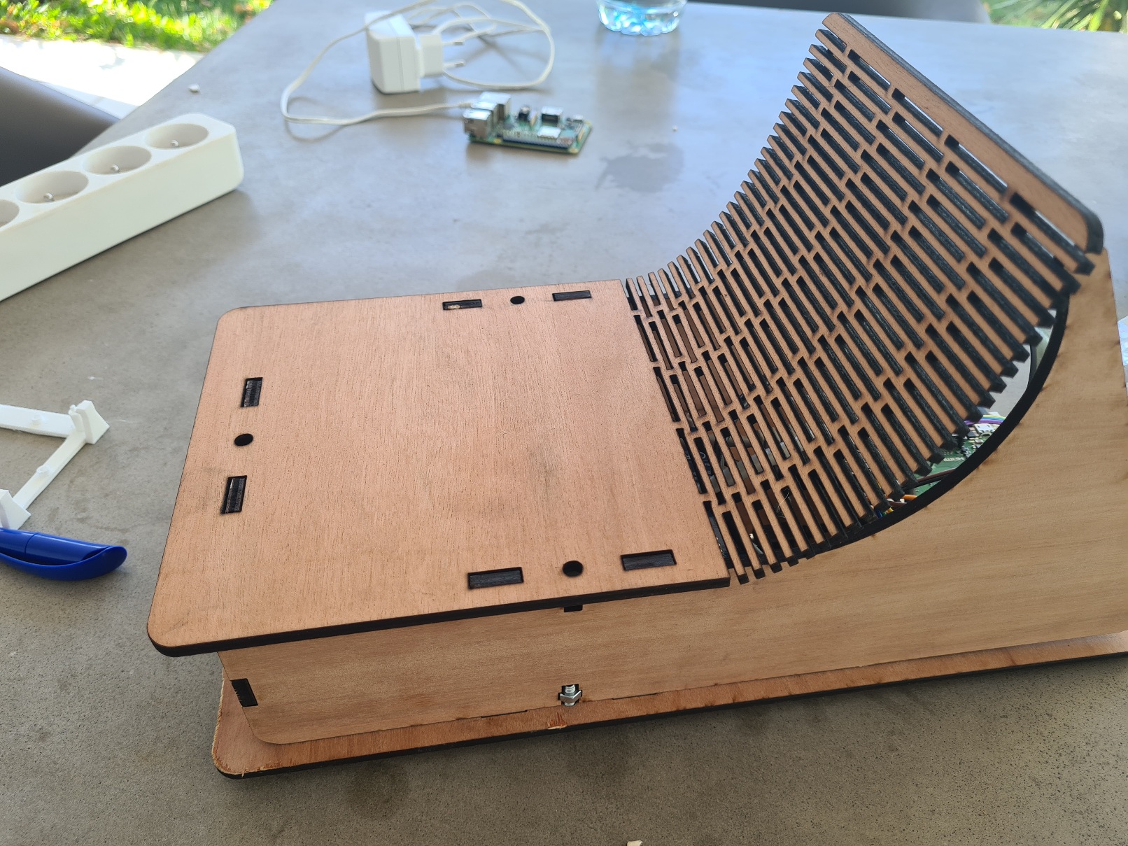
Position the curved part of the rear face, you will have to force a little, but be careful not like a barbarian :)
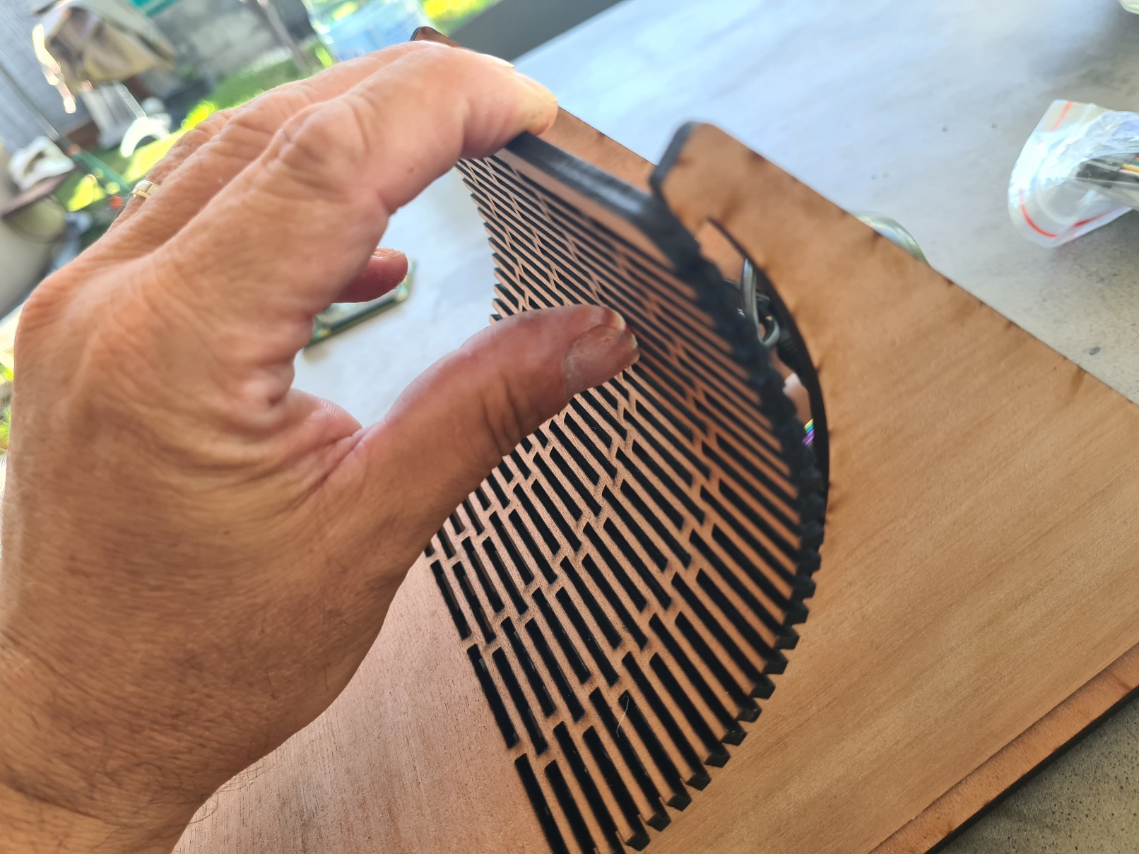
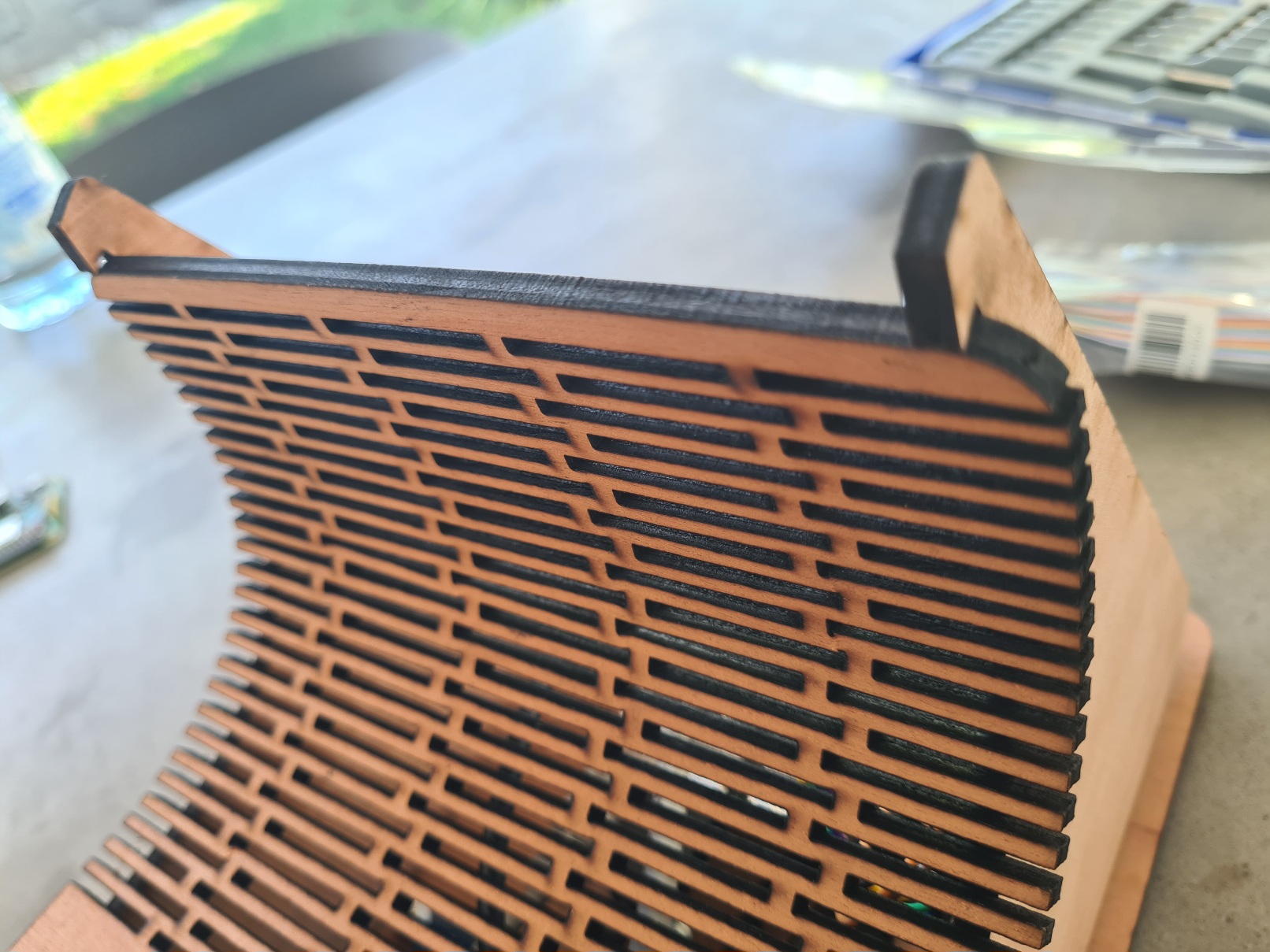
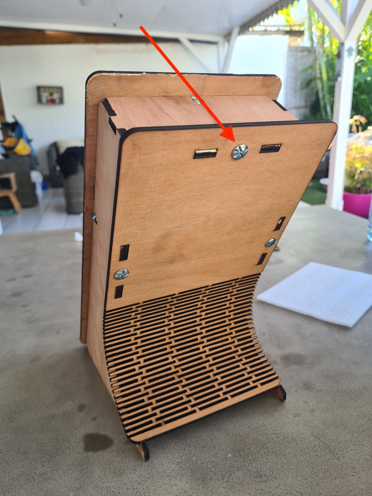
Place the last screw on the rear panel.
You can now tighten all the screws.
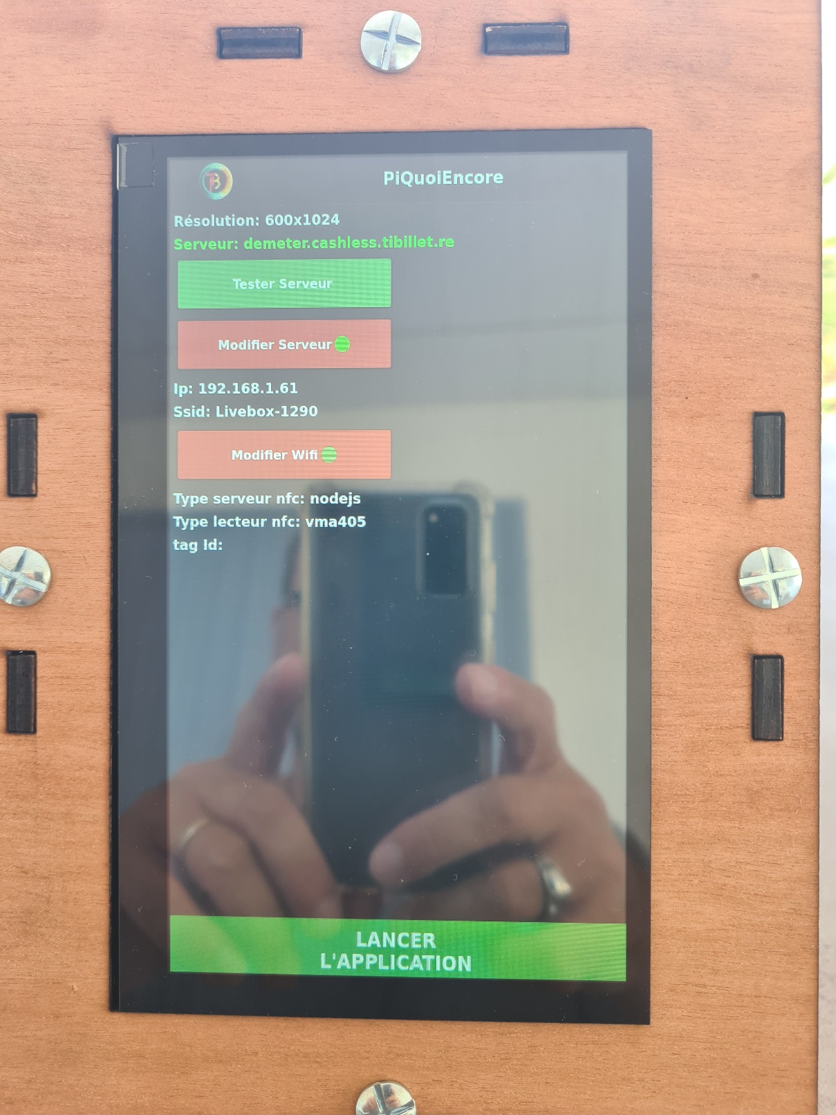
Here's one last test to make sure everything's OK and then you're done.
Connect the power supply and the network.
Place your primary card close to the NFC reader
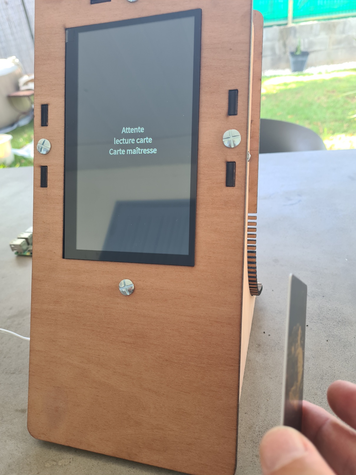
And voilà :
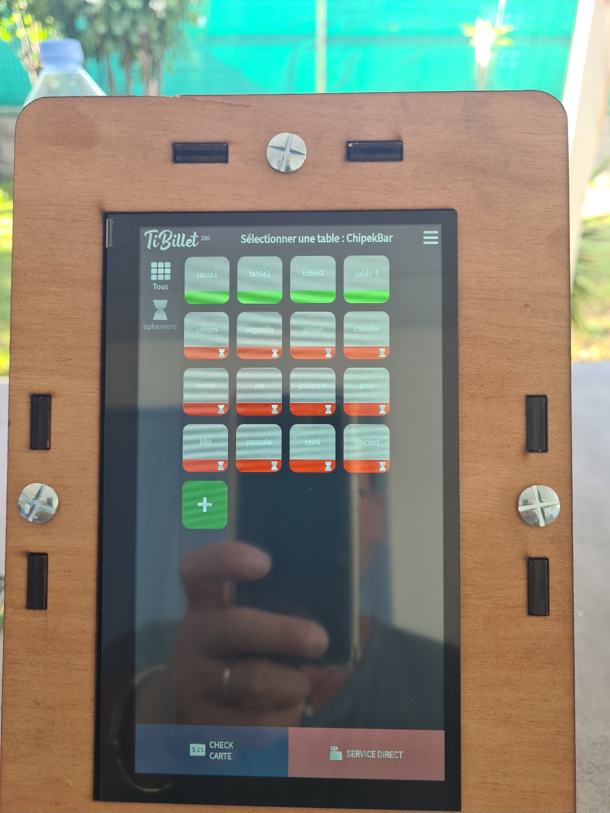
# 5 Body assembly 10inch :
For this section we will only look at assembly and cabling, the software installation section is the same as for the 7-inch.
For laser cutting, use the files in the :
[https://github.com/TiBillet/DIY-point-of-sale-hardware/tree/main/10Pouces](https://github.com/TiBillet/DIY-point-of-sale-hardware/tree/main/10Pouces)
Because the screen doesn't have any fixing brackets, there's an extra piece that will act as a VESA support.
The assembly procedure remains more or less the same, so we'll go through it more quickly, but remember:
- don't overtighten the Roofing bolt & nut 5X16
- The pi must not be powered when the NFC card is wired.
- Use spacers to fix the NFC card.
> Note: you'll need an additional USB-MicroUSB cable, because this time it's not the Pi that powers the screen, but the screen that powers the Pi.
>
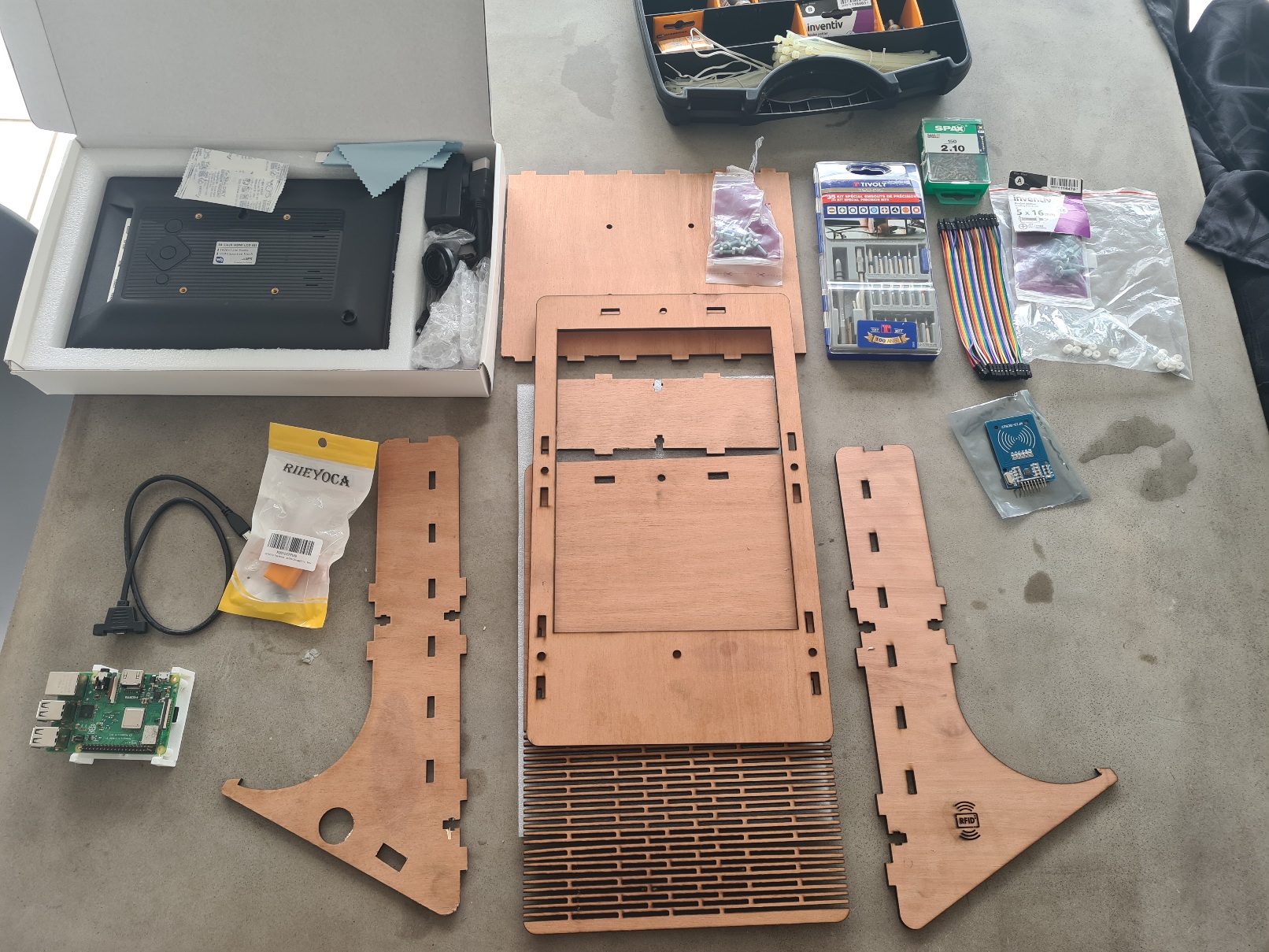
Place the screen on the foam
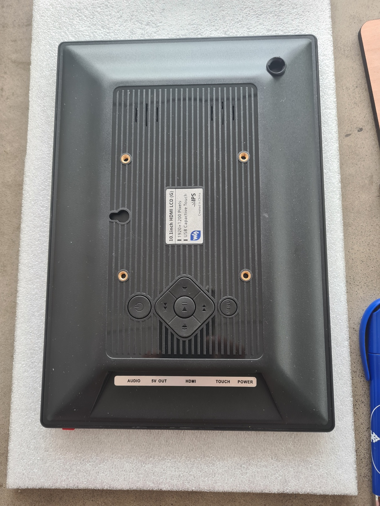
Attach the "VESA" plate :
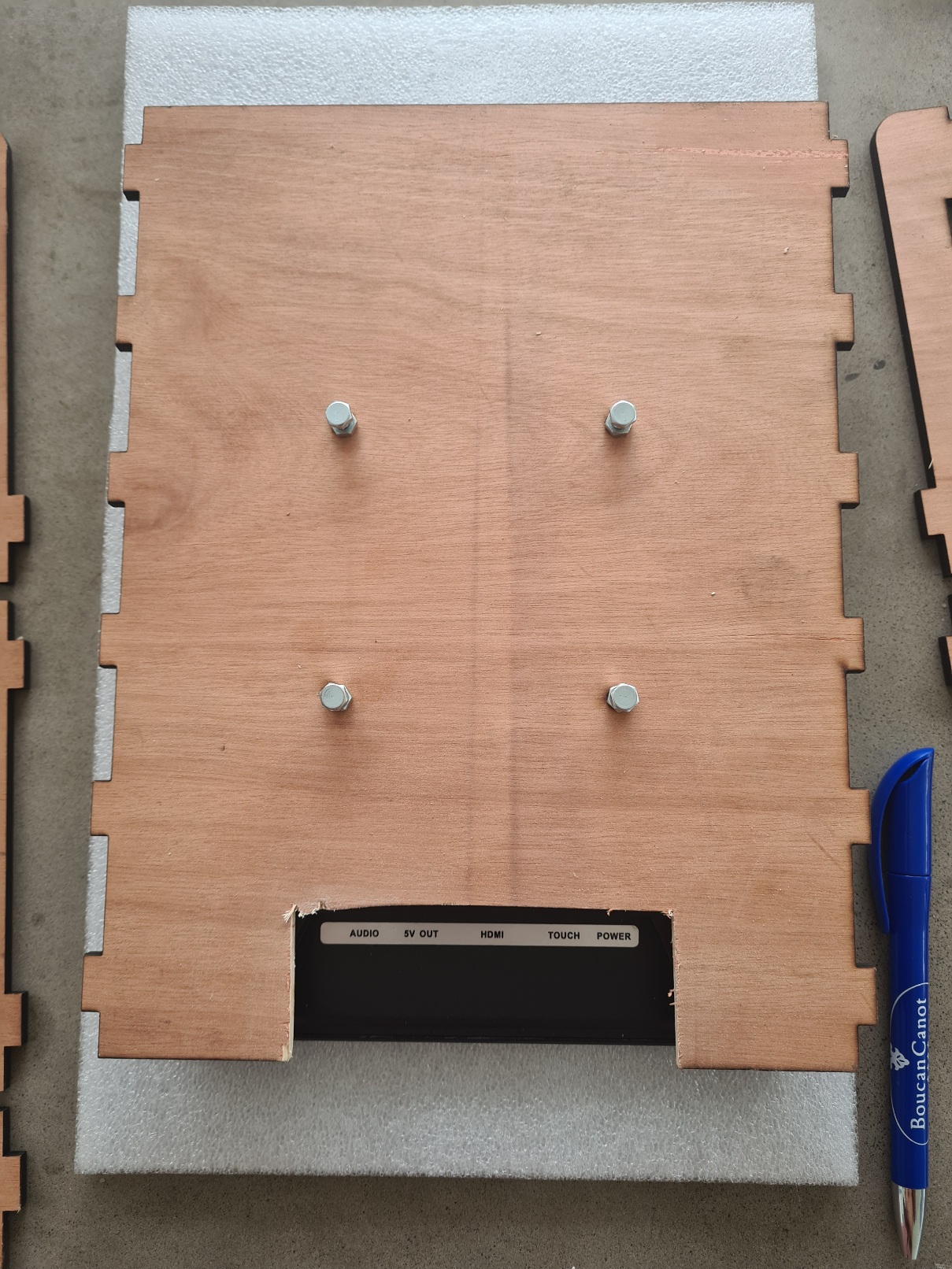
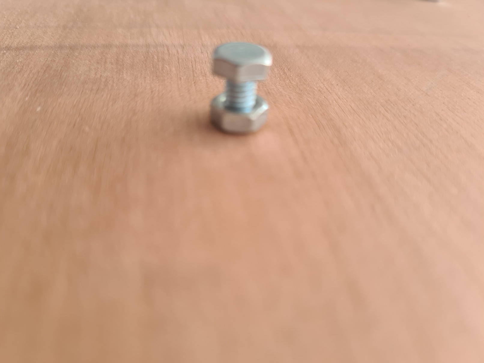
> > Note: If, like me, the screws you have are too long, use the screw nuts:
> >
> Be careful not to tighten it too much, as this could press the buttons on the back of the screen.
Place the front panel on the foam :
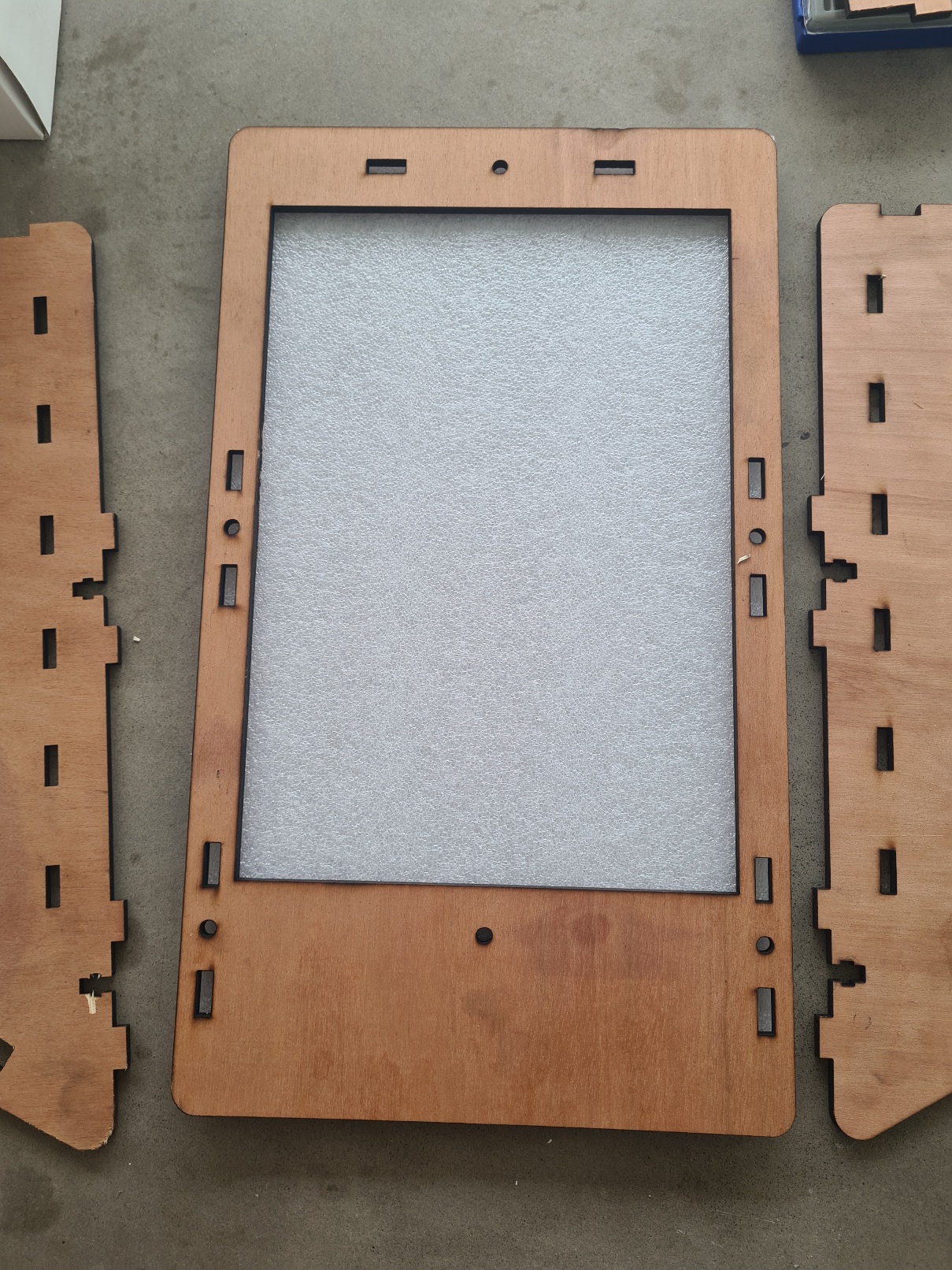
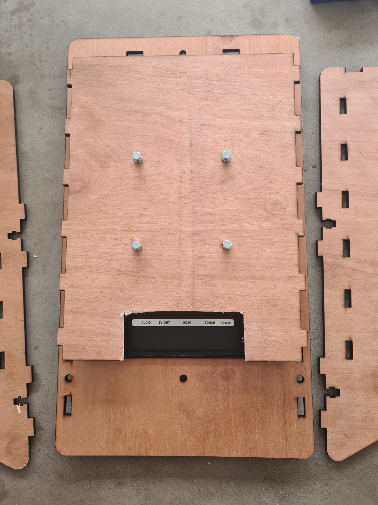
Place the screen :
Place the sides in the notches on the front panel and on the VESA plate :
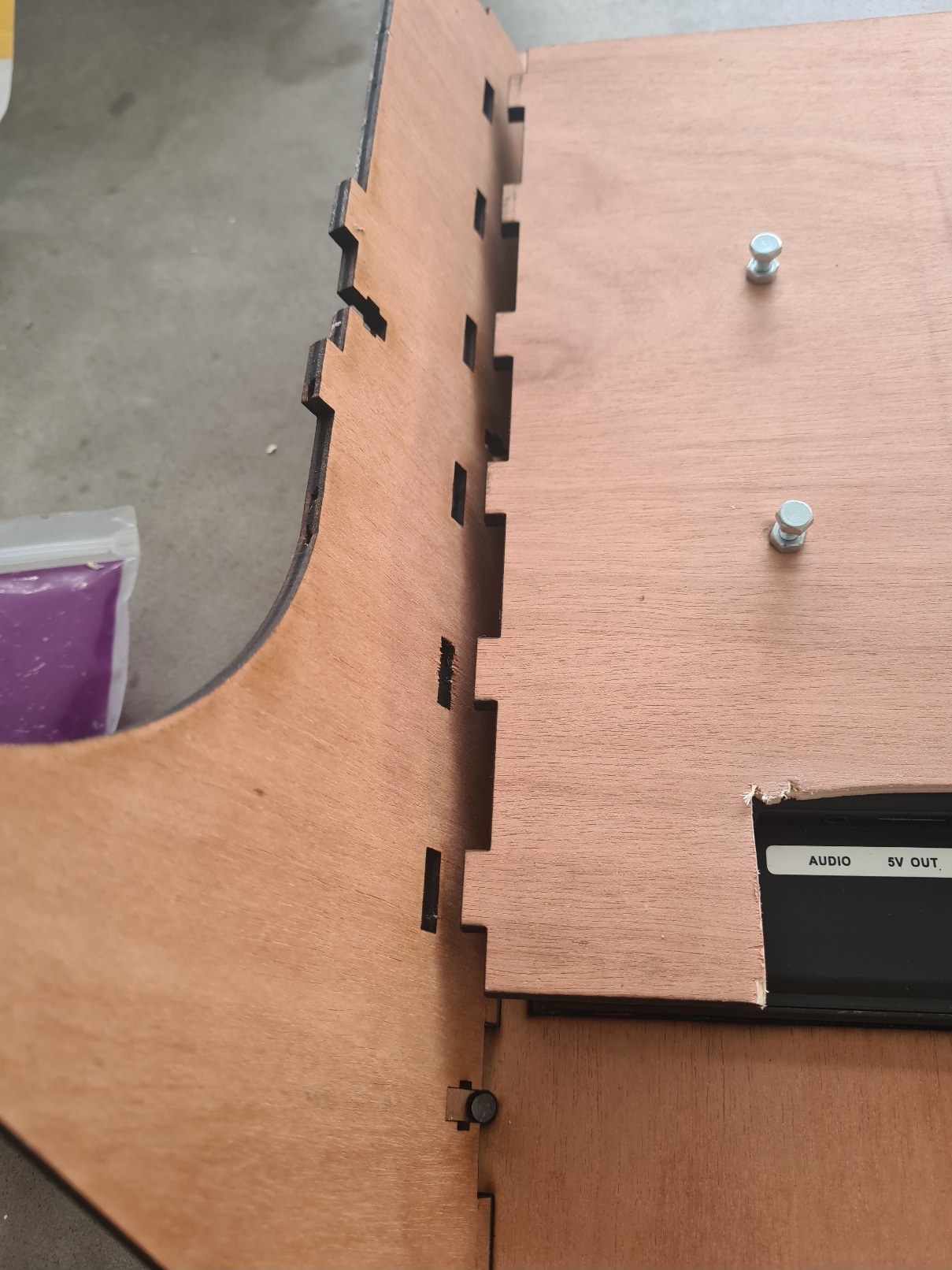
Take the assembly, taking care that the parts do not come loose, then position it normally :
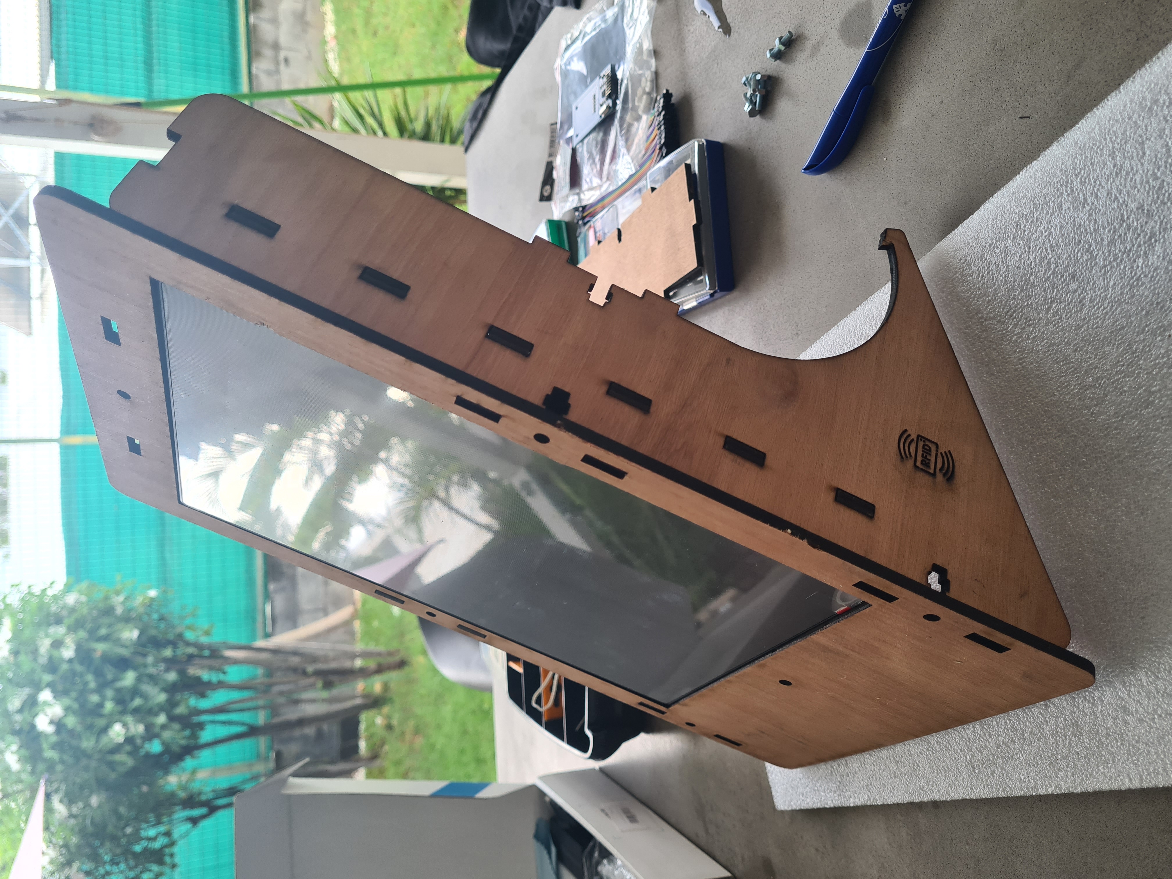
Place the front planel Roofing bolt & nut 5X16 :
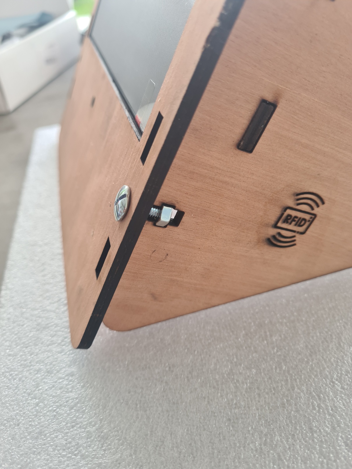
Place the top :
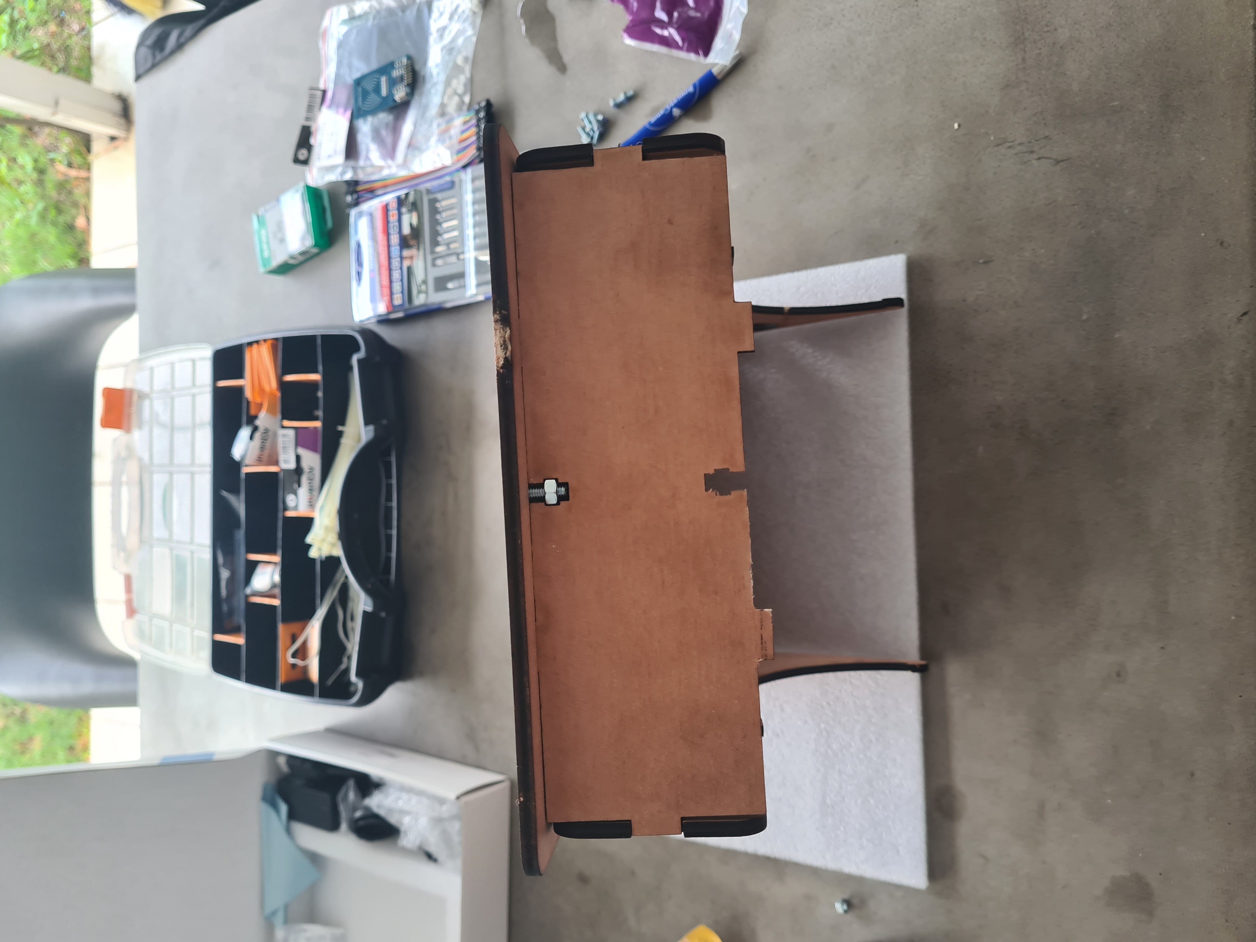
Attach the adapters.
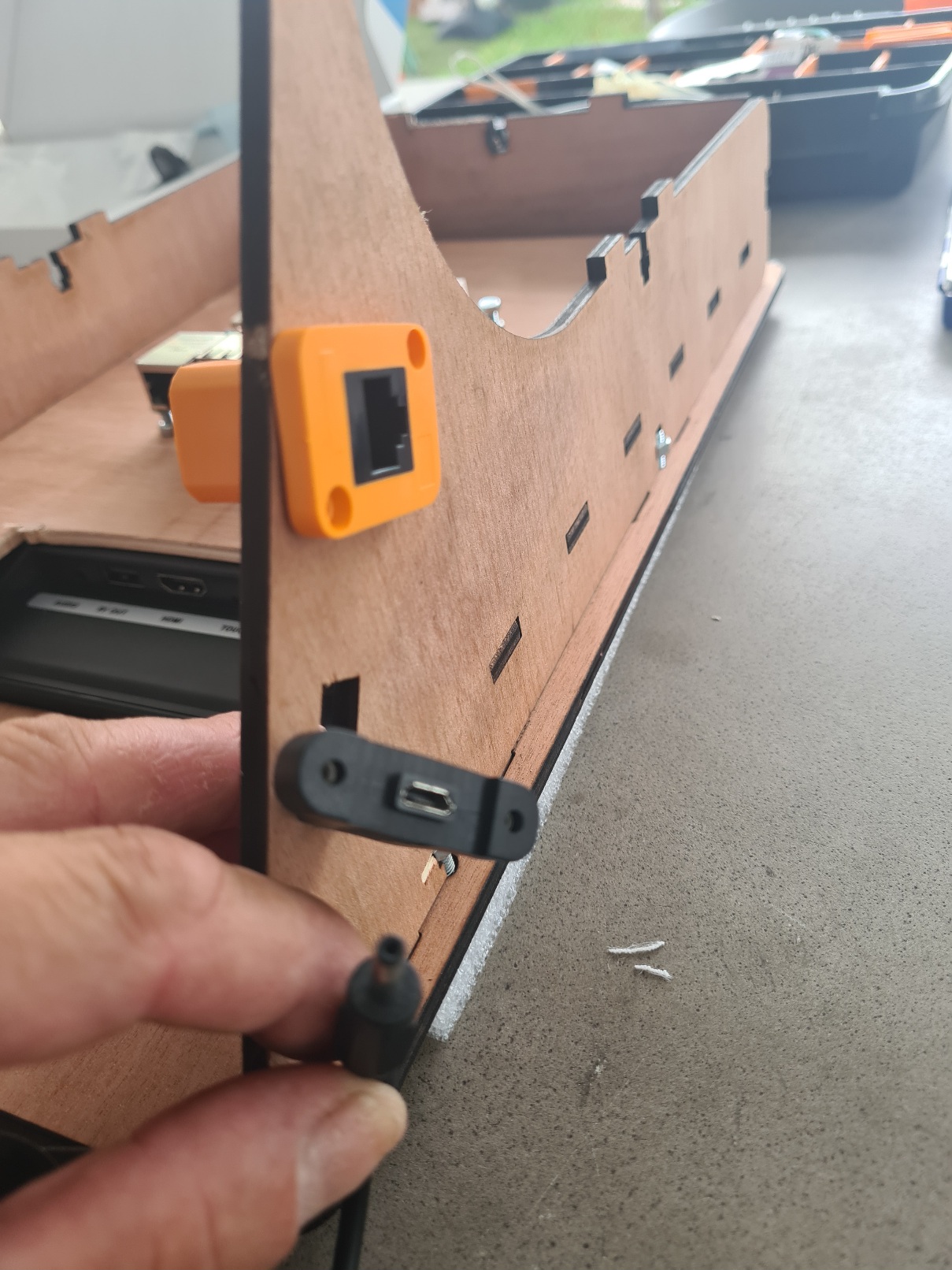
Because this time, it's the screen that powers the Pi, the connectors are different and I don't have the right connector, so I just pass the cable through the hole.
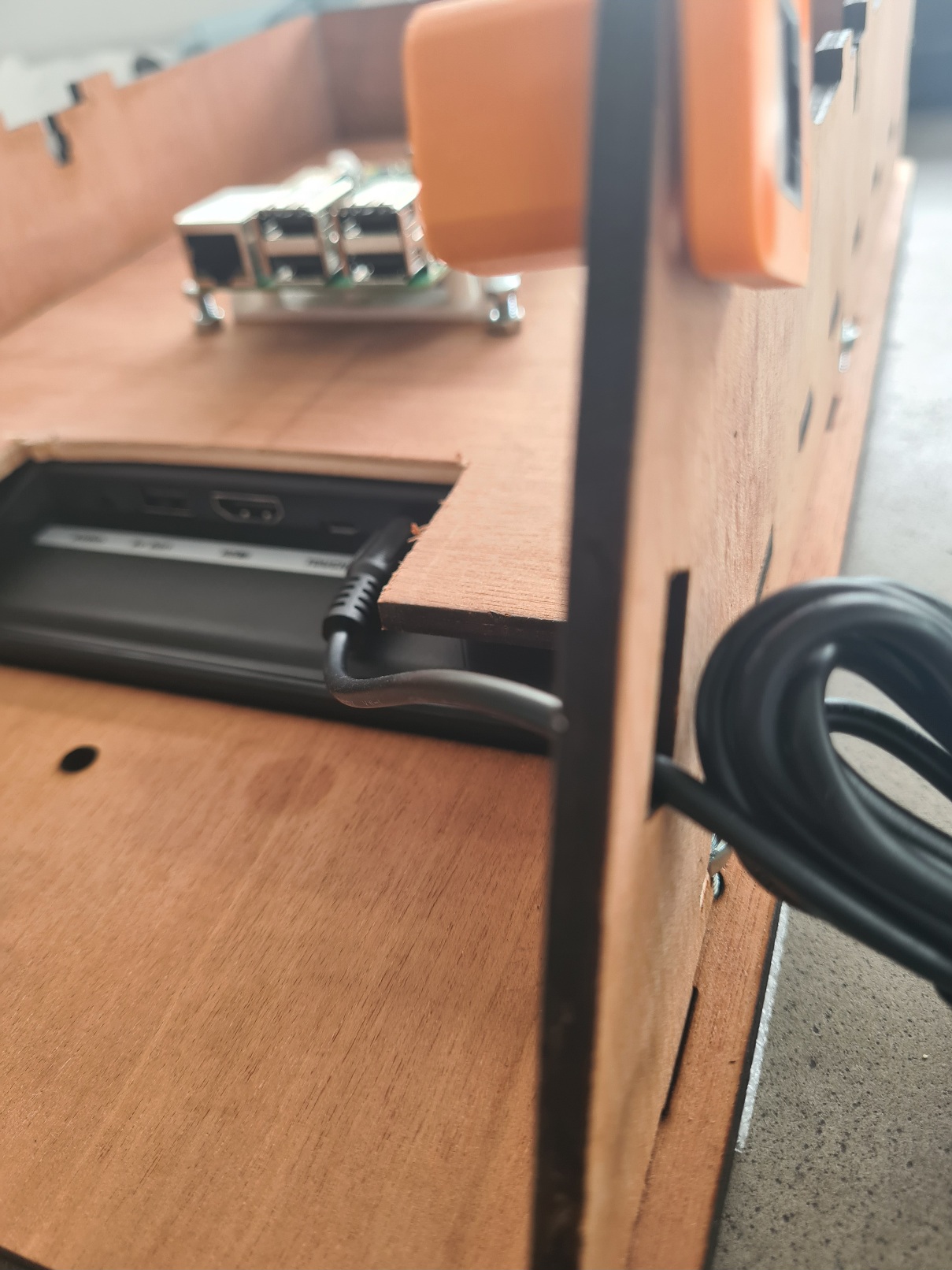
Now, fix the Pi support, cable the NFC reader, the HDMI, the touch screen cable and the cable from the screen to the Pi which powers it. Test before fixing the NFC reader, then also fix it with the spacers.
Place the back panel
Tighten all screws .
And Re-voila :)
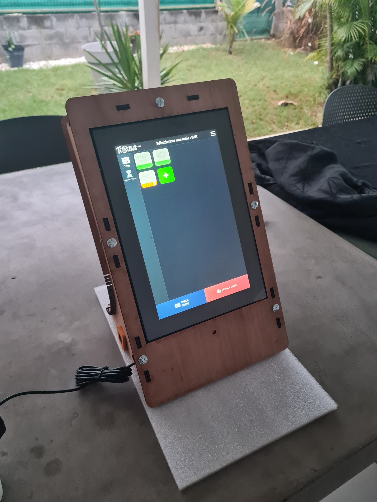
> Don't forget, as in this photo, to put the last screw on the bottom of the screen, even if it serves no purpose, it's nicer :)
# 6 Troubleshooting :
## The NFC reader does not work:
- Check the soldering
- Check the wiring
If everything is OK, change the NFC reader. If it still doesn't work, the Dupont cables are to blame. Test them one by one.
## The touch screen doesn't work:
- Check the wiring
- on the Pi in SSH, access the file /etc/X11/xorg.conf.d/40-libinput.conf .
In the Option "CalibrationMatrix" section you must have one of these 4 values:
"1 0 0 0 1 0 0 0 1"
"0 1 0 0 -1 1 0 0 1"
"-1 0 1 0 -1 1 0 0 1"
"0 -1 1 1 0 0 0 0 1"
In our case, this value must be :
"0 -1 1 1 0 0 0 0 1"
## The screen is not facing the right way:
On the Pi using SSH, access the /boot/config.txt file
In our case you should have this value :
display_rotate=0